IPSEC PART 5: MISCELLANEOUS TOPICS IN IPSEC :

DF BIT IN IPSEC TUNNEL MODE:

capture34

By default, DF bit from INTERESTING TRAFFIC is copied to OUTER IP HEADER imposed by IPSEC END POINT.

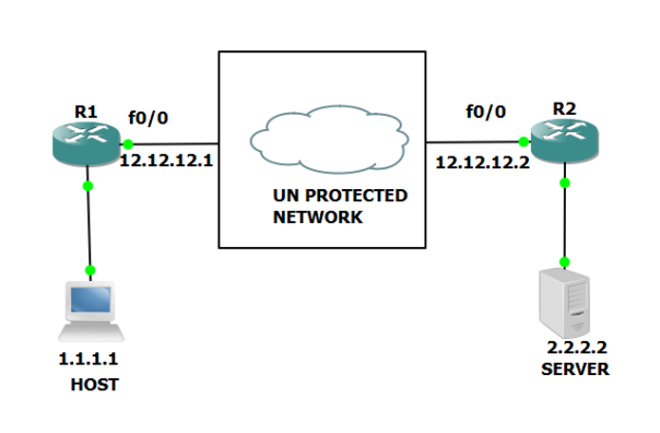
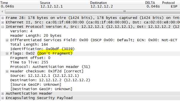
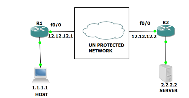
Below is the capture  of ping from 1.1.1.1 to 2.2.2 with DF bit set , INTERESTING TRAFFIC:

fragment-1

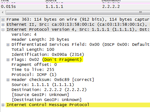
R1 and R2 are IPSEC END POINT  ( TUNNEL MODE), below we can see DF bit is copied into OUTER IP HEADER:

fragment-2

CHECKING IF PACKETS ARE BEING ENCRYPTED/HASHED  AND DECRYPTED/ VERIFIED

R1#show crypto ipsec sa peer 12.12.12.2

interface: FastEthernet0/0
Crypto map tag: ZEE, local addr 12.12.12.1

protected vrf: (none)
local ident (addr/mask/prot/port): (1.1.1.1/255.255.255.255/0/0)
remote ident (addr/mask/prot/port): (2.2.2.2/255.255.255.255/0/0)
current_peer 12.12.12.2 port 500
PERMIT, flags={origin_is_acl,}
#pkts encaps: 11720, #pkts encrypt: 11720, #pkts digest: 11720 
#pkts decaps: 11718, #pkts decrypt: 11718, #pkts verify: 11718

pkts digest: 11720   shows message being hashed

pkts verify: 11718 shows  messages received are being checked for hash and found to have correct hash .

CHANGING  IPSEC  MODE FROM TUNNEL TO MODE WONT TAKE EFFECT IN SOME CASES:

An IPSEC END point determines if the CURRENT TUNNEL MODE should be allowed to  change to TRANSFORM MODE or NOT based on LOCAL PROXY ID.
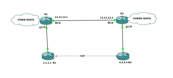
EXAMPLE:

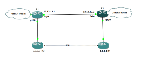
Above R1 and R2 are IPSEC END POINTS in Tunnel mode.

let change the mode to TRANSFOR MODE using :

R1(config)#crypto ipsec transform-set ZEE ah-md5-hmac esp-des
R1(cfg-crypto-trans)#mode transport
R2(config)#crypto ipsec transform-set ZEE ah-md5-hmac esp-des
R2(cfg-crypto-trans)#mode transport

We clear PHASE1 and PHASE2 on R1/R2:

R1#clear crypto isakmp
R1#clear crypto sa

R2#clear crypto isakmp
R2#clear crypto sa

We initiate INTERESTING TRAFFIC FROM 1.1.1.1 to 2.2.2.2

Note even though we change the mode to TRANSPORT but the command was rejected without any  notification from IOS.

R1#show crypto ipsec sa

interface: FastEthernet0/0
Crypto map tag: ZEE, local addr 12.12.12.1

protected vrf: (none)
local ident (addr/mask/prot/port): (1.1.1.1/255.255.255.255/0/0)
remote ident (addr/mask/prot/port): (2.2.2.2/255.255.255.255/0/0)

inbound esp sas:
spi: 0xE22F19EC(3794737644)
transform: esp-des ,
in use settings ={Tunnel, }

outbound esp sas:
spi: 0x8996DB7F(2308365183)
transform: esp-des ,
in use settings ={Tunnel, }

R2#show crypto ipsec sa

interface: FastEthernet0/0
Crypto map tag: ZEE, local addr 12.12.12.2

protected vrf: (none)
local ident (addr/mask/prot/port): (2.2.2.2/255.255.255.255/0/0)
remote ident (addr/mask/prot/port): (1.1.1.1/255.255.255.255/0/0)

inbound esp sas:
spi: 0x8996DB7F(2308365183)
transform: esp-des ,
in use settings ={Tunnel, }

outbound esp sas:
spi: 0xE22F19EC(3794737644)
transform: esp-des ,
in use settings ={Tunnel, }

Tunnel mode remains ” TUNNEL” .

Basically IPSEC END POINT say uses this LOGIC :

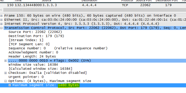
If the PROXY ID shows the INTERESTING TRAFFIC is TRANSIT traffic , the traffic passing through the ROUTER, then MODE can not be set for TRANSPORT MODE  on the router.

On the other hand if PROXY ID shows the ” INTERESTING TRAFFIC” is actually matches the IPSEC TUNNEL SRC and DEST, then MODE can be  allowed to change to  TRANSPORT MODE.

For e.g :

R1 has PROXY ID”access-list permit ip host 12.12.12.1 host 12.12.12.2″ , Since R1 is source PHASE1/PHASE2 with 12.12.12.1 and peer as 12.12.12.2, MODE therefore can changed to ” TRANSPORT” mode  via CLI’s command.

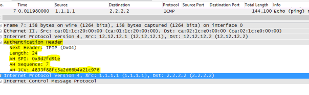
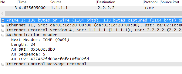
R1 and R2 configured with:

crypto ipsec transform-set ZEE ah-md5-hmac esp-des
mode transport

R1#show crypto ipsec sa

interface: FastEthernet0/0
Crypto map tag: ZEE, local addr 12.12.12.1

protected vrf: (none)
local ident (addr/mask/prot/port): (12.12.12.1/255.255.255.255/0/0)
remote ident (addr/mask/prot/port): (12.12.12.2/255.255.255.255/0/0)

inbound esp sas:
spi: 0x4D47EBA4(1296559012)
transform: esp-des ,
in use settings ={Transport, }

outbound ah sas:
spi: 0x22832CF(36188879)
transform: ah-md5-hmac ,
in use settings ={Transport, }

R2

R2#show crypto ipsec sa

interface: FastEthernet0/0
Crypto map tag: ZEE, local addr 12.12.12.2

protected vrf: (none)
local ident (addr/mask/prot/port): (12.12.12.2/255.255.255.255/0/0)
remote ident (addr/mask/prot/port): (12.12.12.1/255.255.255.255/0/0)

inbound esp sas:
spi: 0x349834B2(882390194)
transform: esp-des ,
in use settings ={Transport, }

outbound esp sas:
spi: 0x4D47EBA4(1296559012)
transform: esp-des ,
in use settings ={Transport, }

Below we can see Tunnel mode has been changed to TRANSPORT MODE.

How about if we change the tunnel mode back to tunnel mode while keeping PROXY ID same?

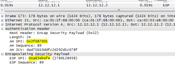
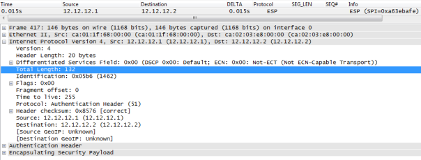
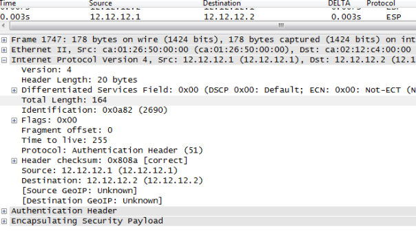
It will introduce another  OUTER IP HEADER ( 12.12.12.1–12.12.12.2) to encapsulate INNER PACKET  ( 12.12.12.1 –12.12.12.2) so it servers no purpose but yes it can be done. Below we can see  ” INTERESTING TRAFFIC  12.12.12.1—-12.12.12.12 is encrypted  then  R1 imposes OUTER IP HEADER SRC 12.12.12.1 DEST 12.12.12.2. note the packet length of 164 bytes.

So we just added 20 bytes extra overhead( OUTER IP HEADER) by using tunnel mode when TRANSPORT could have been used instead.

ine-1

KEY POINT:  Mode can be changed from TUNNEL to TRANSPORT using CLI command   If PROXY ID matches IPSEC TUNNEL SRC and IPSEC TUNNEL DEST on the LOCAL ROUTER.

If not mode remains tunnel, command will be rejected without any notice  by IOS.

Next we will go over DEAD PEER DETECTION.

DEAD PEER DETECTION:t

capture999

Let first see the issue we are trying to solve with DEAD PEER DETECTION.

IPSEC SA ‘s lifetime is 60 MIN by default on Cisco Router.  SA will be maintained until 60  MIN elapsed.  IPSEC END POINTS,  being connected over a IP TRANSPORT  may encounter IP REACHBILITY ISSUE (  some Switch or link on the path inside the IP TRANSPORT was down) but SA will be erroneously maintained in SA database causing INTERESTING TRAFFIC to be black holed until LIFETIME of SA , which is undesirable.

It is obvious we need a mechanism between ISPEC peers to detect if they are reachable/alive.

Various vendors come with their own solutions . Let explore  some of them so we can better appreciate DEAD PEER DETECTION.

HEAR BEAT TECHNIQUE:

IPSEC AB IPSEC B

A  sends  hello at regular interval so A needs to maintain a TIMER for that.

On the other hand, B needs to maintain a  separate TIMER which defines the MAX TIME B can wait to wait for HELLO from A, if none received within that  MAX TIME, B should consider A dead and should purge SA.

Recall that SA are unidirectional, so above B correctly detect A is no  longer reachable because it did not receive  HELLO from A within SET MAX TIME. But A  will continue to send traffic over  SA towards B . Again causing INTERESTING TRAFFIC  to be black holed.

In order for this scheme to be effective B too needs to send HELLO at regular INTERVAL thus  B needs  to maintain a  TIMER for that.  A needs also needs to maintain a TIMER which define MAX TIME that A can wait to receive HELLO from B before considering B as dead and purging SA towards B ( outbound SA). Both A and B must need to agree on common MAX TIME OUT  FOR HELLO. Such scheme are used by EIGRP, OSPF , both of which uses a HELLO INTERVAL and some TIMEOUT value.

So in above scheme we see following  issues:

Both party needs to exchange some info about the HELLO INTERVAL and MAX TIMEOUT for hello. Both needs to maintain two separate TIMERS  :  One for hello interval, the other MAX TIME OUT for hello.

How about if we have not just one but 50,000 IPSEC tunnels ( e.g  VPN Concentrator  at HQ and thousands of remote locations connected to HQ over IPSEC)

That will mean HQ and REMOTE LOCATIONS  needs to exchange 100K messages ( 50,000 Hello from HQ to REMOTE LOCATIONS, 50,000 Hello to HQ) which does not scale well.


KEEP ALIVE TECHNIQUE:

This technique is designed to overcome the limitation of ” HEART BEAT TECHNIQUE” described above.

capture-90

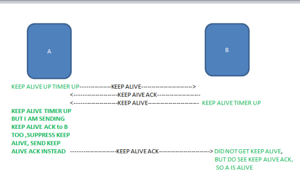
With that scheme, we cut down  a number of messages exchanges to some extent but both party has still need to maintain two timers. BGP uses the same scheme where KEEP ALIVE is suppressed to a particular peer if  BGP update is being sent to that PEER which proves itself the peer is alive.

Again the  this scheme is not scalable when implemented on IPSEC ENDPOINT with thousands of IPSEC TUNNELS.

Cisco implement this scheme  somewhat differently in that ” KEEP ALIVE  are sent at regular interval, transmission of KEEP ALIVE ACK does not suppress KEEP ALIVE as we discussed above.

KEEP ALIVE message  here is  R U THERE ?

KEEP ALIVE ACK  messge here is R U THER ACK ?

crypto isakmp keepalive 10 2 periodic

Router  sends  R u there?  every 10 sec, if R U THERE ACK not received in 10 SEC, then R u there ? messages  are sent every 2 sec.  Peer will try to send 4 to 5 messages if no response is received, remote peer is declared dead.  IN COMING SA for that PEER is purged. This happens even  if local peer is receiving INTERESTING TRAFFIC ON INCOMING SA FROM REMOTE PEER. The sole criteria to declare REMOTE PEER dead is not to receive ” R U THERE ACK from that peer this is the key difference Cisco ‘s implementation of ” KEEP ALIVE” technique discussed above.

For optimal design, both peers must be configured with that feature otherwise traffic will be black holed if remote peer does not implement it and therefore does not require LOCAL PEER to prove its liveliness which cause remote peer to continue to send traffic to local peer (which is no longer alive) until lifetime for SA is up .

ENTERS DEAD PEER DETECTION

Both party will are free to to query if there is question the other party is not alive at any time. There is no need to send any message at regular  interval to prove liveliness to the peer.

This is how the whole scheme works.

Two messages are used:

R U THERE ?

R U THERE ACK

If a peer is receiving  INTERESTING TRAFFIC over  SA, then the traffic itself proves the SENDER is alive, thus SENDER does not need to send any message to prove its liveliness.

How ever if  a peer( A)  has to send some traffic  to the peer ( B) but A  does not see any traffic for specific amount of time( aka worry metric), then A  needs to first verify if B is alive by sending a  ” R U THERE ISKAMP MESSAGE to B. B then needs to send R U THERE ACK to A to prove its liveliness.

The specific amount of time mentioned above is left to VENDOR as per RFC 3706

The beauty of this scheme   Production traffic itself  is used to prove liveliness , message  R U THERE ? is only sent if there is no incoming production traffic for set amount of time ( WORRY METRIC) on a particular SA from a PEER  and there is  INTERESTING NEED TO BE SENT TO THAT PARTICULAR PEER, (which drastically  cut down the amount of  messages) needed to prove liveliness.

Also both party has to maintain just one timer ( worry metric), the maximum amount of idle time to wait when there is no traffic being received from a particular peer  before sending ” R U THERE ? message to verify  remote peer’s liveliness.

HOW DO WE CONFIGURE IT ?

crypto isakmp keepalive XX  YY on-demand

Above XX  is the MAX IDLE TIME local PEER can wait before sending R U THERE ? message to remote peer  to  prove its liveliness  by sending R U THERE  ACK

If R U THERE ACK is not received with in XX time, then LOCAL PEER will send R U THERE ?every  YY SEC,  after sending some messages without any response ( response could be incoming traffic from that remote peer or RU THERE ACK) , Remote peer is declared dead and   INBOUND SA ASSOCIATED WITH REMOTE PEER is purged.

For best design, DPD should be configured on both end, it is possible to configure DPD on one end and still have PHASE1/PHASE2.

IPSEC ADVANCED PART 2: USING AH AND ESP IN IPSEC

Recall IPSEC provides AH and ESP to provide message integrity , message origin authentication, encryption, anti-replay. In summary AH provides:

Message integrity

Message origin authentication.

Anti-replay
ESP provides all the above and plus:

Encryption

It is possible to use AH for MESSAGE INTEGRITY / MESSAGE ORIGIN AUTHENTICATION and ESP for ENCRYPTION  but it introduces  packet , memory and CPU overhead. ESP is  more easy to process than AH.  Moreover,  when using ESP/AH with CRYPTO MAP  SA does not scale well,  as for each PROXY ID,  4 SA have to be maintained(  2 SA for AH, both INBOUND/OUTBOUND, 2 SA for ESP both INBOUND/OUTBOUND)  in SAD ( SA DATABASE).

It is for this reason,  ESP is commonly used to provide for MESSAGE ORIGIN AUTHENTICATION/INTEGRITY and ENCRYPTION  .

Let consider the example where we are using both AH/ESP:

capture999
SET UP:

Traffic between 1.1.1.1 and 2.2.2.2 is INTERESTING TRAFFIC.

R1 and R2 are using AH and ESP in tunnel mode.

R1 's CONFIG:

crypto isakmp policy 1
 hash md5
 encryption des
 authentication pre-share
crypto isakmp key ZEE address 12.12.12.2

crypto ipsec transform-set ZEE ah-md5-hmac esp-des
 mode tunnel

crypto map ZEE 1 ipsec-isakmp
 set peer 12.12.12.2
 set transform-set ZEE
 match address 101

access-list 101 permit ip host 1.1.1.1 host 2.2.2.2
interface FastEthernet0/0
 ip address 12.12.12.1 255.255.255.0
 duplex full
 crypto map ZEE


R2's config:

crypto isakmp policy 1
 hash md5
 encryption des
 authentication pre-share
crypto isakmp key ZEE address 12.12.12.1

crypto ipsec transform-set ZEE ah-md5-hmac esp-des
 mode tunnel

crypto map ZEE 1 ipsec-isakmp
 set peer 12.12.12.1
 set transform-set ZEE
 match address 101

access-list 101 permit ip host 2.2.2.2 host 1.1.1.1

interface FastEthernet0/0
 ip address 12.12.12.1 255.255.255.0
 duplex full
 crypto map ZEE

Below we can see 4 SA are maintained for PROXY ID 1.1.1.1/32 2.2.2.2/32, 2 for AH
2 for ESP.

R1#show crypto ipsec sa

interface: FastEthernet0/0
Crypto map tag: ZEE, local addr 12.12.12.1

protected vrf: (none)
local ident (addr/mask/prot/port): (1.1.1.1/255.255.255.255/0/0)
remote ident (addr/mask/prot/port): (2.2.2.2/255.255.255.255/0/0)

inbound esp sas:
spi: 0x5EDBD553(1591465299)
transform: esp-des ,
in use settings ={Tunnel, }
conn id: 1, flow_id: 1, sibling_flags 80004070, crypto map: ZEE
sa timing: remaining key lifetime (k/sec): (4311709/3362)
IV size: 8 bytes
replay detection support: Y
Status: ACTIVE(ACTIVE)

inbound ah sas:
spi: 0x25B0D720(632346400)
transform: ah-md5-hmac ,
in use settings ={Tunnel, }
conn id: 1, flow_id: 1, sibling_flags 80004070, crypto map: ZEE
sa timing: remaining key lifetime (k/sec): (4311709/3362)
replay detection support: Y
Status: ACTIVE(ACTIVE)

outbound esp sas:
spi: 0xA63EBAFE(2789128958)
transform: esp-des ,
in use settings ={Tunnel, }
conn id: 2, flow_id: 2, sibling_flags 80004070, crypto map: ZEE
sa timing: remaining key lifetime (k/sec): (4311709/3362)
IV size: 8 bytes
replay detection support: Y
Status: ACTIVE(ACTIVE)

outbound ah sas:
spi: 0x2F087001(789082113)
transform: ah-md5-hmac ,
in use settings ={Tunnel, }
conn id: 2, flow_id: 2, sibling_flags 80004070, crypto map: ZEE
sa timing: remaining key lifetime (k/sec): (4311709/3362)
replay detection support: Y
Status: ACTIVE(ACTIVE)

R2 has 4 SA as well.

R2#show crypto ipsec sa

interface: FastEthernet0/0
Crypto map tag: ZEE, local addr 12.12.12.2

protected vrf: (none)
local ident (addr/mask/prot/port): (2.2.2.2/255.255.255.255/0/0)
remote ident (addr/mask/prot/port): (1.1.1.1/255.255.255.255/0/0)
current_peer 12.12.12.1 port 500

inbound esp sas:
spi: 0xA63EBAFE(2789128958)
transform: esp-des ,
in use settings ={Tunnel, }
conn id: 1, flow_id: 1, sibling_flags 80000070, crypto map: ZEE
sa timing: remaining key lifetime (k/sec): (4196692/3182)
IV size: 8 bytes
replay detection support: Y
Status: ACTIVE(ACTIVE)

inbound ah sas:
spi: 0x2F087001(789082113)
transform: ah-md5-hmac ,
in use settings ={Tunnel, }
conn id: 1, flow_id: 1, sibling_flags 80000070, crypto map: ZEE
sa timing: remaining key lifetime (k/sec): (4196692/3182)
replay detection support: Y
Status: ACTIVE(ACTIVE)

outbound esp sas:
spi: 0x5EDBD553(1591465299)
transform: esp-des ,
in use settings ={Tunnel, }
conn id: 2, flow_id: 2, sibling_flags 80000070, crypto map: ZEE
sa timing: remaining key lifetime (k/sec): (4196692/3182)
IV size: 8 bytes
replay detection support: Y
Status: ACTIVE(ACTIVE)

outbound ah sas:
spi: 0x25B0D720(632346400)
transform: ah-md5-hmac ,
in use settings ={Tunnel, }
conn id: 2, flow_id: 2, sibling_flags 80000070, crypto map: ZEE
sa timing: remaining key lifetime (k/sec): (4196692/3182)
replay detection support: Y
Status: ACTIVE(ACTIVE)

Below is the Capture of the traffic from 1.1.1.1 to 2.2.2.2 which is encrypted

capture-34

ORDER OF OPERATION WHEN USING AH/ESP TOGETHER  AT SENDER SITE:

1) INTERESTING TRAFFIC  after  necessary padding if need be, is handed over first to AH to perform HASHING. Once the hashing value(ICV) is calculated, AH header with ICV is created.

2)  INTERESTING TRAFFIC is given to ESP after necessary padding if need be,  to perform ENCRYPTION, the TARGET DATA is now in the form of CIPHER TEXT, ESP header is attached with CIPHER TEXT.

3) Finally  IPSEC imposes  OUTER IP HEADER , followed by AH HEADER and ESP next.

ORDER OF OPERATION WHEN USING AH/ESP TOGETHER  AT RECEIVER SITE:

  1. Received packet is DECRYPTED first, TARGET DATA  is exposed.At this point we have TARGET DATA AND AH HEADER.
  2. Receiver calculates the HASH( ICV) and see if it matches HASH (ICV)  in AH header. If it matches, TARGET DATA is  further processed for routing.


PACKET OVER HEAD:

Below a single ping from 1.1.1.1 to 2.2.2.2 of 64 byte is issued,  notice the ESP/AH over head:

over-head

We can easily calculate the AH/ESP over head as follows:

IP PACKET HEADER  20 BYTES ( OUTER IP PACKET).

132-20=122 bye

122 byte is ORIGINAL IP HEADER( 1.1.1.1,2.2.2.2)+ESP/AH

We already ORIGINAL IP HEADER is 64 BYTE  ( because we issue ping 2.2.2.2 source 1.1.1.1 on HOST1 with size 64 byte)

122-64=58 byte for AH and ESP header.

As discussed in earlier blogs these overhead is variable because of padding required sometimes by different hashing and encryption algorithm. .

IPSEC ADVANCED PART 4: ENCRYPTION ALGORITHIUM

This is a very high level overview of  IPSEC ENCRYPTION ALGORITHM.

IPSEC uses  Block based encryption algorithm i.e a fixed size of data equal to block size is picked at a time for encryption.

IPSEC uses AES / DES /3DES

All these Block based encryption uses ENCRYPTION KEY and IV  to perform ENCRYPTION on TARGET DATA.

WHAT IS IV IN IPSEC?

Encryption key remains same for session duration  If we do not use IV,  and just use ENCRYPTION KEY, same plain text may  have the same  corresponding cipher text( plain text in encrypted form ),  depending upon if AH or ESP is being and the tunnel mode .

IV is a unique random number generated each time packet needs to be encrypted, by seeding IV with ENCRYPTION KEY , we can eliminate the possibility the same plain text may appear same in CIPHER TEXT format.

FROM RFC 3686:

    Only AES Counter mode (AES-CTR) is discussed in this specification.
   AES-CTR requires the encryptor to generate a unique per-packet value,
   and communicate this value to the decryptor.  This specification
   calls this per-packet value an initialization vector (IV). 

So  from high level view the whole process  somewhat looks like this:

ENCRYPTION:

z-5

TARGET DATA must be multiple of ” BLOCK SIZE”   if not,  PADDING  is used so TARGET DATA  length can be multiple of ” BLOCK SIZE” of the ENCRYPTION algorithm.

 Important thing to remember  it is possible to end up with the same size packet after encryption  for different size of “TARGET DATA”   For e.g. if we have 68 byte of IP PACKET, and we are using AES,  it will use some 12 byte of padding so it can be multiple of 16 BYTE BLOCK SIZE, so the TARGET DATA (IP PACKET) is now   80 bytes with padding.

On the other hand if we have  IP PACKET of 80 BYTE ( TARGET DATA), no padding is required, so we see it is possible to end up with same size of ENCRYPTED PACKET SIZE for different “ TARGET DATA” size.

DECRYPTION:

In order to decrypt the CIPHER TEXT, IPSEC END POINT must know, not just ENCRYPTION KEY but also the IV used to encrypt this message, it is for this reason , SENDER always sends  IV in each encrypted message so it can be decrypted  using that IV.

zee-3

ADDITIONAL INFO

AES:

https://tools.ietf.org/html/rfc3602

KEY SIZE: 128, 192 or 256 , represented as aes-128,aes-192,aes-256

IV size 128 bits, Block size: 16 byte

DES:

KEY SIZE :56 BIT

IV SIZE: 8 BYTE ,  BLOCK SIZE: 64 bits

3DES:

https://tools.ietf.org/html/rfc1851#page-2

KEY SIZE:168 bits, IV 8 byte, Block size 64 bits

IPSEC ADVANCED PART 3: AUTHENTICATION ALGORITHMS IN IPSEC

IPSEC uses HMAC which employs “ SECRET KEY” . HMAC can use various hashing algorithms .Below is a very brief  high level overview of the common authentication algorithm used in IPSEC. Before we start, Authentication in IPSEC refers: To verify if data is not altered in transit( Integrity) and  the data comes from the legitimate source( message authentication)

Basically, by factoring “SECRET KEY” in computing HASH  ,  we  are implicitly verifying if the source of the packet is a legitimate or not.

All these HASHING ALGORITHM picks a chunk of  data equal to BLOCK SIZE at a time from “TARGET DATA” and and calculates  HASH as shown below:

zee-7


Each hashing algorithm has a specific “BLOCK SIZE” and “hash value” size.  For e.g. HMAC-MD5-96 uses BLOCK SIZE of 64 BYTES, HASH VALUE is 96 bits long.

If for some reason TARGET DATA is less than or not the multiple of 64 byte (e.g  MD5) padding is used to ensure TARGET DATA’s length is the multiple of BLOCK SIZE.

That is an important thing to remember as it is possible to end up with the same size packet after hashing for different size of “TARGET DATA”   For e.g. if we have 68 byte of IP PACKET, it will use some 60 byte of padding so it can be multiple of 64 BYTE BLOCK SIZE, so the TARGET DATA (IP PACKET) here becomes the size of 128 byte.

On the other hand if we  IP PACKET of 128 BYTE ( TARGET DATA), no padding is required, so we see it is possible to end up with same size of ENCRYPTED PACKET SIZE for different “ TARGET DATA” size.

Additional info:

(https://www.ietf.org/rfc/rfc2403.txt)

 HMAC-MD5-96: Hash value: 96 bit, Block size:64 BYTE

https://tools.ietf.org/html/rfc4868

 HMAC-SHA-256: hash 256 bit, Block size: 64 byte

 HMAC-SHA-384: hash 384 bit, Block size: 128 byte

 HMAC-SHA-512: hash 512 bit, Block size: 128 byte


IPSEC ADVANCED PART1: USING AH ONLY

AH only provides message integrity, data origination verification,  anti-reply  just like ESP but ESP can also provide encryption which AH can’t

This blog is only focused on using AH to provide message integrity, data origination verification, and anti-reply for our INTERESTING TRAFFIC.

AH HEADER:

Uses 51 as a protocol identifier in IP packet.

FROM RFC 4302:

ah-header-1

NEXT HEADER is  1 BYTE

PAYLOAD LENGTH: 1 BYTE

RESERVED: 2 BYTES ( all zeros , not used)

SECURITY PARAMETERS INDEX ( SPI): 4 byte

SEQUENCE NUMBER:  4 BYTE

ICV: Variable ( depends upon hashing algorithm chosen in phase2)

What is ICV?

ICV stands for INTEGRITY CHECK VALUE, which is a fancy way to say hash value.Each HASHING algorithm have their own ways to represent computed hash in different bit length.

For example: Cisco currently supports following HASHING ALGORITHM UNDER AH:

md5-hmac uses ICV of 96 bits

HMAC SHA1 uses ICV of 96 bits

HMAC SHA2 256-bit , ICV 128 bits

HMAC SHA2 384-bit, ICV 192 bits

R3#show tcp brief
TCB Local Address Foreign Address (state)
67B21A54 3.3.3.3.15906 4.4.4.4.179 ESTAB
HMAC SHA2 512-bit, ICV 256 bits

AH header length must be the multiple of 4 byte( or 32-bit word). if we look at the header’s fields, we see all fields when combined ( excluding ICV) is 12 byte which is multiple of 4. The only thing that could result in rendering AH header not to be multiple of 4 is ICV field’s length.

As mentioned before, ICV length depends upon the HASHING ALGORITHM  being used. The length of ICV is communicated when HASHING ALGORITHM is negotiated in PHASE2.

Let say Hashing Algorithm chosen uses ICV of 10 bytes, so if we add 10 bytes of ICV with 12 byte of other fixed fields in AH header, we arrive at 22 byte which is not the multiple of 4. It is for this reason padding is used inside ICV field such that over all AH header length terminates on 4 BYTE boundary.

Above we can see all the currently supported hashing algorithm in AH  use ICV length which is multiple  of 4 byte ( i.e 32 bit word), we should not be seeing any need for padding with in AH header.

AH IN TUNNEL MODE:

FROM RFC 4302:

AH in tunnel mode:

ah-advanced-9

capture999

Above ” INTERESTING TRAFFIC” is defined between  host ( 1.1.1.1) and server ( 2.2.2.2)

Host 1 sends a ping  to 2.2.2.2, which is received by R1( IPSEC END POINT), which triggers R1 to establish IPSEC tunnel.

Below is the encrypted traffic  of INTERESTING TRAFFIC ( 1.1.1.12.2.2.2)

ah-advanced-3

Above  inner packet is ping packet with SRC IP 1.1.1.1 , DST 2.2.2.2, it is also an original packet.

Outer IP HEADER with SRC IP 12.12.12.1 DEST 12.12.12.2 is NEW IP HEADER imposed  by IPSEC END POINT R1.

Above Inner packet( ping) from HOST1 to SERVER ( 2.2.2.2) is right below AH header. AH header is inserted between this INNER PACKET ( WHICH ACTS AS A PAYLOAD FOR AH) and OUTER IP HEADER ( which is imposed by IPSEC END POINT : R1)

Note AH’s pay load  ( inner packet which is actually a PING) is not encrypted.

Above Hash value  ( ICV) is computed over Original IP HEADER and its PAY LAOD ( ICMP), OUTER IP HEADER ( not including mutable fields), ICV is then inserted inside AH header which is placed right after OUTER IP PACKET.

EFFECTIVE MTU FOR THE ABOVE EXAMPLE:

The effective MTU can be calculated by subtracting AH header’s length+ OUTER IP PACKET SIZE  from IP MTU.

In our case AH header is 24 byte for the given hashing algorithm,  OUTER IP HEADER is 20 BYTE so 1500-24-20=1456byte

So HOST and SERVER must be configured with IP MTU of 1456 to avoid fragmentation  on R1 and R2 or  HOST/SERVER is not using IPMTU PATH DISCOVERY PROCESS or PATH DISCOVER PROCESS is broken for some reason.

IPSEC IN TRANSPORT MODE:

In some cases, we do not need to use IPSEC in tunnel mode, because there is no need to introduce new IP HEADER.  for e.g there is no need to encapsulate inner packet because inner packet is  using route able public IP.

EXAMPLE:

capture34

Above Traffic is IPSEC protected  right on the host and SERVER, i.e  R1 and R2 are not doing any IPSEC functions,  all IP SEC functions are performed by HOST and SERVER. This mode is called Transport mode.

FROM RFC 4302:

AH in TRANSPORT MODE:

.ah-header-56

In our case, Host 1.1.1. issues a ping to 2.2.2.2 ( SERVER), and we are using AH in transport mode.

ah-advanced067

Note there is only one IP header ( compare it with IPSEC in tunnel mode), this IP header is from the original IP PACKET.

Hashing is performed on IP PACKET’s header ( not including mutable fields,) ICMP pay load and the then result is placed inside ” ICV field” inside AH header. AH header is then inserted between IP HEADER and its PAYLOAD( ICMP).

EFFECTIVE MTU FOR THE ABOVE EXAMPLE:

The effective MTU can be calculated by subtracting AH header’s length from IP MTU.

In our case AH header is 24 byte for the given hashing algorithm,  if IP MTU is  1500 byte so effective  IP MTU is 1476 byte.

We must modify HOST and SERVER  IP  MTU to 1476 byte to avoid fragmentation on R1 and R2 that is  if HOST/SERVER is not using  IPMTU PATH DISCOVERY PROCESS or PATH DISCOVER PROCESS is broken for some reason.

Rule of Thump:

Always use IP MTU 1400 when dealing with IPSEC to accomate all kinds of over-head.

What if I do not have access to MACHINES generating ” INTERESTING TRAFFIC to set MTU and PATH MTU DISCOVERY PROCESS is broken?

We can use IP TCP ADJUST-MSS command  but it has on effect on IPSEC IN TRANSPORT MODE . Please read below for detail.

BASICS OF ” IP TCP ADJUST-MSS ” command:

(ONLY VALID FOR TCP BASED INTERESTING TRAFFIC)

Recall  host machines wishing to use TCP  based communication ( e.g www, telnet) first performs three-way TCP hand shake. In TCP hand shake, they exchange MSS ( MAX segment size ) which is : TCP SEGMENT LENGTH-TCP HEADER

MSS  represents the max segment size a TCP receiver willing to accept .

MODERN MACHINES calculates MSS as follows:

Current IP MTU-20( IP HEADER)-20 ( TCP HEADER)=MSS

For IP MTU of 1500 byte, it will be 1500-20-20=1460

That value is then compared with ” TCP RECEIVE BUFFER” and the lower value is then advertised during TCP hand shake as MSS

Each party then sets the MSS in TCP hand shake message, the lower value is then chosen for the TCP session.

EXAMPLE

R1 ( 12.12.12.1) f0/0———f0/012.12.12.2( R2)

R1#show ip interface f0/0
Internet address is 12.12.12.1/24
MTU is 1400 bytes

R2#show ip interface f0/0
Internet address is 12.12.12.2/24
MTU is 1500 bytes

Above R1  has IP MTU of 1400 so it has calculated MSS as 1360 (  because 1400-20 -20), R2 has IP MTU of 1500 so R2 MSS is 1460.

Below I establish a TCP session between R1 and R2 ( I used BGP to generate TCP based traffic). Note MSS is negotiated as 1360 ( Lower value announced by R1)

R1#show tcp brief
TCB Local Address Foreign Address (state)
68F0A61C 12.12.12.1.179 12.12.12.2.50453 ESTAB
R1#show tcp tcb 68F0A61C
SNIP!!
Datagrams (max data segment is 1360 bytes):
R2#show tcp brief
TCB Local Address Foreign Address (state)
67A857FC 12.12.12.2.50453 12.12.12.1.179 ESTAB


R2#show tcp tcb 67A857FC

SNIP

Datagrams (max data segment is 1360 bytes)

Now we have basic idea what is MSS and how it is calculated .

We can ask  any one router on the path  to peer into TCP hand shake SYN message and changes MSS if certain condition is met. Let see an example:

USING IP TCP ADJUST-MSS:

capture-56

Above we need to set IP MTU of 1400 on R3/R4 but  have no access to these routers,or IP PATH MTU DISCOVERY is broken for some reason,   currently they are sending larger ip packet than 1400 which is causing fragmentation on R1 and R2.  We can not do anything for UDP based traffic between R3 and R4, such traffic will continue to be fragmented but for TCP based application we can instruct either R1 or R2 ( it does not matter , just one router who sees TCP hand shake between the R3–R4, in our case both R1/R2 sees , so anyone can be chosen, I just chose R1)

On R1 under f0/0  we configure:

R1#show running-config interface f0/0
Building configuration...

Current configuration : 107 bytes
interface FastEthernet0/0
 ip address 12.12.12.1 255.255.255.0
 ip tcp adjust-mss 1360
 duplex full

Above we are asking R1 to set MSS in TCP hand shake message, now the question is: which TCP HAND SHAKE message, we see  two TCP SYN messages:

From R3 to R4 carrying MSS 1460,

From R4 to R3 carrying MSS 1460.

The answers is  R1 will set the MSS 1360 in both messages if it sees both messages on F0/0, note that “ip tcp adjust-mss 1360″ is has no direction ( ingress or egress)  because this command for both direction:

Note that  to fore TCP session to use a particular MSS, we just need to modify MSS in any one TCP SYNC message during TCP hand shake.

Because R1 is configured with the command ” ip tcp adjust-mss 1360″, R1 peers into TCP SYN messages from R3 to R4 , compares the MSS which is 1460 , set by R3, since 1430 is > than 1360 , R1 therefore swaps 1460 out by 1360.

Following capture taken between R3–R1, R3 is using MSS of 1460 before  this messages gets to R1.

capture-ah-78

Following is the capture taken between R1–R2, note R1 has swapped  MSS 1460 seen above with 1360 in the TCP SYN PACKET sent to R4:In our example, R3 happens to send fist TCP SYN message to R4.  Since R4 ‘s MSS is 1460 and MSS received in TCP SYN  from R3 is 1360, R4 therefore sets its MSS as 1360 because it is lower  in its TCP SYN message to R3.

R1 sees this SYN from R4 to R1 and sees MSS as 1360. Since this MSS is not less than the one specified under f0/0 on R1 i.e 1360. R1 therefore leaves the MSS as it is.

If the situation was reverse i.e if R4 happened to send fist TCP SYN message, R1 would swap 1460 out with 1360 , R3 therefore sees MSS 1360 from in TCP SYN message from R4 and therefore  sets its own MSS in the TCP SYN message to R4.  R1 would see that MSS but would not swap it out because 1360 is not less than 1360 specified under f0/0 on R1.

Above we used fo/0 on R1 to modify MSS in TCP SYN which is not optimum place  here is why:

The command ” ip tcp adjust-mss 1360″ not just force MSS in TCP SYN between R3–R4, rather it forces this MSS in all TCP SYN messages flowing among others. Now all the other hosts needlessly are forced to use MSS of 1360 even though they can support MSS of 1460.

In our example, the best place to apply this command is either g1/0 on R1 or R2,

By using “ip tcp adjust-mss 1360” under g1/0 on R1, R1 will only modify MSS in TCP SYN ingressing/egressing the interface thus other hosts’s are not longer forced to use MSS of 1360.

Alternatively we could use this command on R2 under g1/0 as well.

Key point to remember: MSS in TCP SYN has to be larger than the MSS specified using ” ip tcp adjust-mss, for router to swap it out. If MSS in TCP SYN is less than or equal to  MSS specified using ” ip tcp adjust-mss, router does not swap it out.

IPSEC IN TRANSPORT MODE AND IP TCP ADJUST-MSS COMMAND:

 Why  the command ip tcp adjust-mss XX has no impact on MSS  when AH/ESP  in transport mode is being used between two HOST MACHINES?

Recall AH calculates ICV over IP HEADER ( not counting mutable fields) IP PAY LOAD, AH’s header contents.

In our example, AH will calculate the ICV over IP PACKET HEADER,( not counting mutable fields) PAY LOAD ” TCP” and AH header’s contents.

capture-56Above host machines R3 and R4  , using IPSEC in transport mode.

Both these  routers are sending   INTERESTING TRAFFIC  TCP( 3.3.3.3–4.4.4.4) over IPSEC tunnel in transport mode.  We configured R1 to modify MSS to 1360 in all TCP SYN message it sees on f0/0 but yet MSS remains 1460:

R4#show tcp tcb 68F64E0C | begin Data
Datagrams (max data segment is 1460 bytes):
Rcvd: 75 (out of order: 0), with data: 37, total data bytes: 745
Sent: 72 (retransmit: 1 fastretransmit: 0),with data: 37, total data bytes: 745

R3#show tcp brief
TCB Local Address Foreign Address (state)
68F3DAF0 3.3.3.3.23684 4.4.4.4.179 ESTAB
R3#show tcp tcb 68F3DAF0 | begin Data
Datagrams (max data segment is 1460 bytes):
Rcvd: 75 (out of order: 0), with data: 39, total data bytes: 783
Sent: 77 (retransmit: 1 fastretransmit: 0),with data: 38, total data bytes: 764

Below is why:

R1 is looking for TCP  SYN,  When R1 sees the IP packet  carrying TCP SYN, it first check the IP PROTOCOL FIELD TO SEE IF THE IP PAY LOAD IS TCP, but it instead it sees AH as next protocol in IP HEADER’ PROTOCOL FIELD, R1 therefore does not modify MSS as it is not TCP   message as far as R1 is concerned. R1   does not check into AH header to see if the next pay load  field in AH  shows TCP because R1 has no intelligence about AH or instructed via configuration to do so.

Same goes for ESP in TRANSPORT MODE.

IPSEC IN TUNNEL MODE AND IP TCP ADJUST-MSS COMMAND:

Both AH/ESP in tunnel mode have no issue with when using IP TCP ADJUST-MSS command as long as this command is used at least on one of IPSEC END POINT.

For example, we have another router in between R1 and R2 , say Rn. Then even we configure that command, it will not effect because the Rn will sees the packet  IP PAY LOAD as ESP ( because TCP is encrypted) so from Rn perspective it is not TCP so it will not be able to set MSS.

The logic works this way:

When the INITIATOR receives the interesting traffic, it first peers into IP PACKET and see if there is TCP pay load carrying TCP SYN. It happens before any hashing/encrpytion is performed. If it does see TCP PAY LOAD carrying TCP SYN,  and it sees MSS in TCP SYN is larger than the one specified by the command IP TCP ADJUST-MSS, it swaps the MSS out with the specified one  now hashing .encryption is performed on the IP PACKET with swapped MSS.

EXAMPLE:

capture-90

Above” Interesting traffic is defined  between 3.3.3.3 and 4.4.4.4.

R1 f0/0 is configured with ip tcp adjust-mss 1360. R1 and R2 are IPSEC end points using AH in tunnel mode.

3.3.3.3 and 4.4.4.4 both use IP MTU of 1500 so they calculate their MSS as 1460 ( 1500- 20 ( IP HEADER)-20 ( TCP HEADER) )

But we can  TCP session is using MSS 1360 because of the command ip tcp adjust-mss 1360 under f0/0 on R1.

R3#show tcp brief
TCB Local Address Foreign Address (state)
67B21A54 3.3.3.3.15906 4.4.4.4.179 ESTAB
R3#show tcp tcb 67B21A54


Datagrams (max data segment is 1360 bytes):

IPSEC PART X: ANTI-REPLAY

capture-replay

ANTI-REPLAY

What is the issue?

In order to understand ANTI-REPLAY, let see the issue we are  trying to mitigate :

Above host 1.1.1.1 wants to login to server 2.2.2.2, this communication is IPSEC protected. HOST 1.1.1.1 sends login credentials in packets . Attacker records them and later ( while the same IPSEC SA is still active),replays them to R2 and able to login to SERVER 2.2.2.2

ENTERS ANTI-REPLAY FEATURE:

It is important to understand this feature does not eliminate the issue , it does mitigate it.

There are four components in ANTI-REPLAY

  1. SEQUENCE NUMBER
  2. WINDOW
  3. Tracking the HIGHEST sequence numbers on the RECEIVER
  4.  Tracking the sequence numbers for a range of packets on the RECEIVER

In discussion below:

SENDER refers to  IPSEC END POINT which is sending the INTERESTING TRAFFIC

RECEIVER refers  IPSEC END POINT receiving the INTERESTING TRAFFIC.

SENDER will sequence each packet it sends to RECEIVER over a specific  IPSEC SA to RECEIVER, starting from 1.

SENDER will increment the sequence number by 1 for each packet it sends.

RECEIVER  will have a window which defines the range of packets,by default it is 64. WINDOW SIZE defines the range of packets’s sequence number SERVER needs to keep track of. RECEIVER will also track HIGHEST SEQUENCE number it has seen/received at any given time.

EXAMPLE#1

Let see an example to understand it:

SENDER ( R1) has 100 PACKETS  to send, also assume  no packet has been sent so far to RECEIVER ( R2).

SENDER (R1) sends first 80  PACKETS to RECEIVER ( R2).

RECEIVER (R2) has thus far seen HIGHEST SEQUENCE NUMBER 80, RECEIVER has window size 64 of packets. Next RECEIVER calculates the  range as shown below:

X-W+1——-X

WHERE :

X: is the highest number seen, it is 80 in this example.

W: is the window size in packets. it is 64

so the range is:

80-64+1—80

17——80

So valid range is from 17 to 80, this means RECEIVER WILL keep track of packets with sequence number 17–80

EXAMPLE#2

Let takes another example to see how all this fit together.

SENDER ( R1) has sends 200 packets ( sequence number starts from 1 to 200).  RECEIVER only receives   packets with SEQUENCE# 100-200.

In our case, X is 200, window size is 64 so valid range is :

200-64+1—-200

137—-200

Any packet withe sequence number below 137, will be considered a REPLAY ATTACK and therefore will be discarded right away without any further processing; REPLAY COUNTER will be incremented.

Any packet with sequence number # 137 to 200, will be  further processed for REPLAY ATTACK CHECK.

Recall RECEIVER is tracking sequence number from 137—200. If RECEIVER sees the sequence number in the arriving packet matches the sequence number it has already received, it will be considered ” REPLAY ATTACK”;  PACKET will be discarded , REPLAY COUNTER will be incremented.  For e.g let say arriving packet has a sequence number of 138, Receiver then checks if it has received this sequence number, if it has, RECEIVER considers it REPLAY ATTACK, drop the packet, increment the REPLAY COUNTER.

Let assume  SENDER sends a packet with sequence number 201.

RECEIVER sees the sequence number 201, and knows it is now the new HIGHEST SEQUENCE NUMBER IT has SEEN.  RECEIVER now consider X to be 201 , new window is calculated:

201-64+1—201

138–201

RECEIVER now keeps track of sequence number 138 to 201

Now any packet with sequence # below 138, will be discarded by the RECEIVER, REPLAY COUNTER will be incremented.

Any packet with sequence number greater than 201, will be received, and new WINDOW will be calculated.

Any packet with sequence number 138–201, is further processed for REPLAY CHECK, if sequence number matches sequence number that RECEIVER  has previously seen, will be considered REPLAY ATTACK , REPLAY counter will be incremented.

HOW DO WE CONFIGURE IT?

A 32 bit counter inside the ESP/AH header is used for sequencing. Once  counter hits the highest number possible ( 4294967295), IPSEC SA will be reset, a new PHASE 2 will be initiated.

SENDER always assume REPLAY is on by default as per RFC 4303.  It is up to the receiver to use it or not.  If Receiver does want to use it, it must inform  the SENDER so SEQUENCE NUMBER can be initialized i.e both parties set their counters to zero.

RFC4303:

The field is mandatory and MUST always be present even if the
   receiver does not elect to enable the anti-replay service for a
   specific SA.  Processing of the Sequence Number field is at the
   discretion of the receiver, but all ESP implementations MUST be
   capable of performing the processing described in Sections 3.3.3 and
   3.4.3. Thus, the sender MUST always transmit this field, but the
   receiver need not act upon it (see the discussion of Sequence Number
   Verification in the "Inbound Packet Processing" section (3.4.3)
   below)
   The sender's counter and the receiver's counter are initialized to 0
   when an SA is established.  (The first packet sent using a given SA
   will have a sequence number of 1; see Section 3.3.3 for more details
   on how the sequence number is generated.)  If anti-replay is enabled
   (the default), the transmitted sequence number must never be allowed
   to cycle.  Thus, the sender's counter and the receiver's counter MUST
   be reset (by establishing a new SA and thus a new key) prior to the
   transmission of the 2^32nd packet on an SA.

On the SENDER site, it is already enabled by default. On the RECEIVER, we can enable it in two ways:

GLOBALLY:

ROUTER(CONFIG)#crypto ipsec security-association replay window-size XX

ROUTER(CONFIG)#crypto ipsec security-association replay disable

When enabled globally, it enable ANTI-RELAY on all IPSEC SA on the RECEIVER.

PER  SA BASIS:

Alternatively, we can use under a CRYPTO MAP/PROFILE to  enable it on a specific SA. it provides  a lot more granularity.

CRYPTO MAP  ZEE

set security-association replay window-size 

CRYPTO PROFILE ZEE

set security-association replay window-size

POTENTIALS ISSUES WITH ANTI-REPLAY:

It is possible legitimate  traffic can be dropped by the RECEIVER  erroneously  as REPLAY-ATTACK.

Let explore some examples that could cause it:

HEAVY PACKET LOSS:

A heavy packet loss  between SEDER and RECEIVER will move the CURRENT WINDOW rapidly, therefore increasing the chance  previously sent packets may arrive OUTSIDE the CURRENT WINDOW and dropped as REPLAY ATTACK.

AT THE SENDER

EGRESS QOS:

QOS is applied after ENCRYPTION,  using QOS we can prioritize several traffic flows (VOIP, SQL, WEB)  flowing over a IPSEC TUNNEL.  QOS will order the packets in the on the egress queue, thus causing the legitimate packets to arrive at the RECEIVER which fall outside the RANGE or WINDOW on the RECEIVER. RECEIVER therefore declare erroneous as  REPLAY ATTACK.

AT THE RECEIVER:

RE ASSEMBLY:

All fragmented packets at the receiver are reassembled first before handed over to IPSEC’ DECRYPTION process. This introduces delay which could cause some reassembled packets to be outside the CURRENT WINDOW at the receiver ( some packets which were sent later than reassembled packets, will not go though this additional delay thus delivered to IPSEC DECRYPTION process earlier) .

INGRESS QUEUING :

Most of the routers/switches perform QOS on egress, but depending upon platform/vendor, we can have ingress queuing as well. For example Juniper MX series perform ingress queuing. Cisco 3560 performs ingress queuing.

INGRESS QUEUING (QOS) can re order the packets which may fall outside the CURRENT WINDOW at the RECEIVER, again erroneously dropped as REPLAY ATTACK.

TRANSIT NETWORK:

Transit network can have multiple paths with different link speeds for the given destination which can re order the packets. Similarly, varying network load on different routers/switches within TRANSIT network , may  re-order the packets( CPU may be  more busy on some routers than others, which introduces re ordering).  Transit network may mark down QOS marking , again, introducing re-ordering of packets.

 HOW DO WE FIND IF PACKETS ARE BEING DROPPED AS REPLAY-ATTACK?

show crypto ipsec sa peer X.X.X.X detail

R1#show crypto ipsec sa peer 2.2.2.2 detail

interface: FastEthernet0/0
Crypto map tag: ZEE, local addr 12.12.12.1

protected vrf: (none)
local ident (addr/mask/prot/port): (1.1.1.1/255.255.255.255/0/0)
remote ident (addr/mask/prot/port): (2.2.2.2/255.255.255.255/0/0)
current_peer 12.12.12.2 port 500
PERMIT, flags={origin_is_acl,}
#pkts encaps: 9, #pkts encrypt: 9, #pkts digest: 9
#pkts decaps: 9, #pkts decrypt: 9, #pkts verify: 9
#pkts compressed: 0, #pkts decompressed: 0
#pkts not compressed: 0, #pkts compr. failed: 0
#pkts not decompressed: 0, #pkts decompress failed: 0
#pkts no sa (send) 0, #pkts invalid sa (rcv) 0
#pkts encaps failed (send) 0, #pkts decaps failed (rcv) 0
#pkts invalid prot (recv) 0, #pkts verify failed: 0
#pkts invalid identity (recv) 0, #pkts invalid len (rcv) 0
#pkts replay rollover (send): 0, #pkts replay rollover (rcv) 0
##pkts replay failed (rcv): 0

HOW DO WE FIX IT?

So there is trade off, we can increase the WINDOW on the RECEIVER, so  reordered packets when arrived at RECEIVER are still be WITHIN the WINDOW therefore will be not dropped but then we are also increasing the chance for someone to send spoofed packets with sequence number within the CURRENT WINDOW.

Moreover there is no specific guidelines what is the OPTIMUM WINDOW SIZE  .

Cisco recommends using 1024 WINDOW SIZE

RFC 4303:

   A minimum window size of 32 packets MUST be supported when 32-bit
   sequence numbers are employed; a window size of 64 is preferred and
   SHOULD be employed as the default.  Another window size (larger than
   the minimum) MAY be chosen by the receiver.  (The receiver does NOT
   notify the sender of the window size.)  The receive window size
   should be increased for higher-speed environments, irrespective of
   assurance issues.  Values for minimum and recommended receive window
   sizes for very high-speed (e.g., multi-gigabit/second) devices are
   not specified by this standard.

IPSEC PART IX: IPSEC’S SA SCALABILTY ISSUE IN CRYPTO MAP BASED IPSEC

capture34

Above both R1/R2 have single PROXY ID to identify ” INTERESTING TRAFFIC” between 1.1.1.1 and 2.2.2.2

Below we can see there is pair( INBBOUND SPI/OUTBOUND SPI) of IPSEC SA for each PROXY ID .

Each IPSEC SPI  allows uni-directional communication,  so for bi -directional communication,  we see two IPSEC SPI( INBOUND SPI/OUTBOUND SPI) per PROXY ID.

Since R1 has single PROXY ID , therefore we see only TWO SPI ( INBOUND/OUTBOUND):

R1#show crypto ipsec sa

protected vrf: (none)
 local ident (addr/mask/prot/port): (1.1.1.1/255.255.255.255/0/0)
 remote ident (addr/mask/prot/port): (2.2.2.2/255.255.255.255/0/0)


Truncated!!

local crypto endpt.: 12.12.12.1, remote crypto endpt.: 12.12.12.2
 path mtu 1500, ip mtu 1500, ip mtu idb FastEthernet0/0
 current outbound spi: 0xCDF97AB4(3455679156)
 PFS (Y/N): N, DH group: none

TRUNCATED!!

inbound esp sas:
 spi: 0xB6058795(3053815701)
 transform: esp-3des esp-md5-hmac ,
 in use settings ={Tunnel, }


TRUNCATED!!

outbound esp sas:
 spi: 0xCDF97AB4(3455679156)
 transform: esp-3des esp-md5-hmac ,
 in use settings ={Tunnel, }

Same goes for R2:

R2#show crypto ipsec sa

interface: FastEthernet0/0
 Crypto map tag: ZEE, local addr 12.12.12.2

protected vrf: (none)
 local ident (addr/mask/prot/port): (2.2.2.2/255.255.255.255/0/0)
 remote ident (addr/mask/prot/port): (1.1.1.1/255.255.255.255/0/0)
 current_peer 12.12.12.1 port 500
 PERMIT, flags={origin_is_acl,}
 #pkts encaps: 1, #pkts encrypt: 1, #pkts digest: 1
 #pkts decaps: 1, #pkts decrypt: 1, #pkts verify: 1
 #pkts compressed: 0, #pkts decompressed: 0
 #pkts not compressed: 0, #pkts compr. failed: 0
 #pkts not decompressed: 0, #pkts decompress failed: 0
 #send errors 0, #recv errors 0

local crypto endpt.: 12.12.12.2, remote crypto endpt.: 12.12.12.1
 path mtu 1500, ip mtu 1500, ip mtu idb FastEthernet0/0
 current outbound spi: 0xB6058795(3053815701)
 PFS (Y/N): N, DH group: none

inbound esp sas:
 spi: 0xCDF97AB4(3455679156)
 transform: esp-3des esp-md5-hmac ,
 in use settings ={Tunnel, }


outbound esp sas
 spi: 0xB6058795(3053815701)
 transform: esp-3des esp-md5-hmac ,
 in use settings ={Tunnel, }
 
R2#

So if we have two PROXY ID on R1/R2 , we will see another IPSEC SA pair.It means if we have 100 PROX IDS on R1, we need to maintain 100 IPSEC SA pairs. Maintaining  IPSEC SPI  takes valuable CPU/memory resources. It is for this reason   CRYPTO MAP BASED IPSEC does not scale well as the number of PROXY IDS go up ( i.e number of ACL statements).

IPSEC PART VIII: COMMON ISSUES IN PHASE2

capture34

When investigating phase 2’s  issues,looking at IPSEC debug on RESPONDER is a lot more helpful than looking at DEBUG ISAKMP output. For example, if there is mismatch issue with encryption,hashing, tunnel mode, Proxy ID,single ISAKMP NOTIFICATION MESSAGE WITH CODE”PROPOSAL NOT CHOSEN 3″ is sent. By looking at this message, we can not tell what caused this: Is it PROXY ID? ENCRYPTION TYPE? So it is a lot better to look at DEBUG CRYPTO IPSEC on RESPONDER when investigating PHASE2 ‘s issue.

For a successful phase2 ‘s negotiation following must be true:

  1. Matching encryption, hashing, DH
  2. Matching tunnel mode
  3. Proxy ID ( ACL) on RESPONDER/INITIATOR SHOULD MIRROR EACH OTHER  ( It is possible to have successful PHASE2 negotiation even when PROXY ID does not mirror , but it will cause intermittent connectivity  issue for production traffic, we  will demonstrate using an example towards the end of this post  under ” MORE ON PROXY ID”, but for optimum design, PROXY ID must mirror)

We will introduce issues and see what debug looks like on RESPONDER. This  way we can train ourselves to identify the issue by just looking at debug.

PROXY IDS DO NOT MIRROR:

R1:

crypto isakmp policy 1
 encr 3des
 hash md5
 authentication pre-share
 lifetime 120
crypto isakmp key ZEE address 12.12.12.2
crypto ipsec transform-set ZEE esp-3des esp-md5-hmac
 mode tunnel
crypto map ZEE 1 ipsec-isakmp
 set peer 12.12.12.2
 set transform-set ZEE
 match address 101

access-list 101 permit ip host 1.1.1.1 host 2.2.2.2

R2:

crypto isakmp policy 1
 encr 3des
 hash md5
 authentication pre-share
 lifetime 120
crypto isakmp key ZEE address 12.12.12.1


crypto ipsec transform-set ZEE esp-3des esp-md5-hmac
 mode tunnel
crypto map ZEE 1 ipsec-isakmp
 set peer 12.12.12.1
 set transform-set ZEE
 match address 101


access-list 101 permit ip host 2.2.2.2 host 3.3.3.3 

DEBUG  ISAKMP ON R1 ( INITIATOR)

*Dec 2 11:41:04.503: ISAKMP:(1059): processing NOTIFY PROPOSAL_NOT_CHOSEN   protocol 3

DEBUG ISAKMP ON R2( RESPONDER)

ISAKMP:(1059): phase 2 SA policy not acceptable! (local 12.12.12.2 remote 12.12.12.1)
*Dec 2 11:41:34.587: ISAKMP: set new node 2135090770 to QM_IDLE
*Dec 2 11:41:34.587: ISAKMP:(1059):Sending NOTIFY PROPOSAL_NOT_CHOSEN protocol 

Not enough info to pinpoint if PROXY IS is the cause, however if we see DEBUG CRYPTO IPSEC ON RESPONDER,  we can easily pinpoint:

Dec 2 11:44:18.367: IPSEC(validate_proposal_request): proposal part #1,
(key eng. msg.) INBOUND local= 12.12.12.2:0, remote= 12.12.12.1:0,
local_proxy= 2.2.2.2/255.255.255.255/256/0,
remote_proxy= 1.1.1.1/255.255.255.255/256/0,
protocol= ESP, transform= NONE (Tunnel),
lifedur= 0s and 0kb,
spi= 0x0(0), conn_id= 0, keysize= 0, flags= 0x0
*Dec 2 11:44:18.367: Crypto mapdb : proxy_match
src addr : 2.2.2.2
dst addr : 1.1.1.1
protocol : 0
src port : 0
dst port : 0
R2#
*Dec 2 11:44:18.367: Crypto mapdb : proxy_match
src addr : 2.2.2.2
dst addr : 1.1.1.1
protocol : 0
src port : 0
dst port : 0
*Dec 2 11:44:18.367: map_db_find_best did not find matching map
*Dec 2 11:44:18.367: IPSEC(ipsec_process_proposal): proxy identities not supported

ENCRYPTION DOES NOT MATCH:

We have normalized the set up and just introduced mismatch encryption:

Debug crypto isakmp on R1/R2

NOTIFY PROPOSAL_NOT_CHOSEN protocol

R1:

crypto ipsec transform-set ZEE esp-aes esp-md5-hmac

R2:

crypto ipsec transform-set ZEE esp-3des esp-md5-hmac
debug crypto isakmp on R1 ( INITIATOR):

*Dec 2 11:49:55.351: ISAKMP:(1061): processing NOTIFY PROPOSAL_NOT_CHOSEN protocol 3
debug  crypto isakmp on R2 ( RESPONDER)

Dec 2 11:50:25.411: ISAKMP:(1061): IPSec policy invalidated proposal with error 256
*Dec 2 11:50:25.411: ISAKMP:(1061): phase 2 SA policy not acceptable! (local 12.12.12.2 remote 12.12.12.1)
*Dec 2 11:50:25.411: ISAKMP:
R2#set new node -760315767 to QM_IDLE
*Dec 2 11:50:25.411: ISAKMP:(1061):Sending NOTIFY PROPOSAL_NOT_CHOSEN protocol 3

Agin not enough info to pinpoint mismatch encryption is the cause but debug crypto ipsec does pinpoint it:

DEBUG CRYPTO IPSEC ON R2( RESPONDER)

*Dec 2 11:52:36.227: IPSEC(validate_proposal_request): proposal part #1,
 (key eng. msg.) INBOUND local= 12.12.12.2:0, remote= 12.12.12.1:0,
 local_proxy= 2.2.2.2/255.255.255.255/256/0,
 remote_proxy= 1.1.1.1/255.255.255.255/256/0,
 protocol= ESP, transform= NONE (Tunnel),
 lifedur= 0s and 0kb,
 spi= 0x0(0), conn_id= 0, keysize= 128, flags= 0x0
*Dec 2 11:52:36.235: Crypto mapdb : proxy_match
 src addr : 2.2.2.2
 dst addr : 1.1.1.1
 protocol : 0
 src port : 0
 dst port : 0
R2#
*Dec 2 11:52:36.235: IPSEC(ipsec_process_proposal): transform proposal
 not supported for identity:
 {esp-aes esp-md5-hmac }

MISMATCH HASHING:

We have normalized the set up, introduced only hashing mismatch:

R1(config)#crypto ipsec transform-set ZEE esp-3des esp-sha512-hmac
R2(config)#crypto ipsec transform-set ZEE esp-3des esp-md5-hmac
DEBUG CRYPTO ISAKMP ON R1( INITIATOR):
*Dec 2 11:59:35.351: ISAKMP (1063): received packet from 12.12.12.2 dp
R1#ort 500 sport 500 Global (I) QM_IDLE
*Dec 2 11:59:35.351: ISAKMP: set new node -241107808 to QM_IDLE
*Dec 2 11:59:35.351: ISAKMP:(1063): processing HASH payload. message ID = 4053859488
*Dec 2 11:59:35.351: ISAKMP:(1063): processing NOTIFY PROPOSAL_NOT_CHOSEN protocol 3

DEBUG CRYPTO ISAKMP ON R2 (RESPONDER)

*Dec 2 12:00:05.391: ISAKMP:(1063): IPSec policy invalidated proposal with error 256
*Dec 2 12:00:05.395: ISAKMP:(1063): phase 2 SA policy not acceptable! (local 12.12.12.2 remote 12.12.12.1)
*Dec 2 12:00:05.395: ISAKMP: set new node -1199250418 to QM_IDLE
*D
R2#ec 2 12:00:05.399: ISAKMP:(1063):Sending NOTIFY PROPOSAL_NOT_CHOSEN protocol 3
DEBUG CRYPTO IPSEC ON R2 ( RESPONDER):

Dec 2 12:00:05.379: IPSEC(validate_proposal_request): proposal part #1,
 (key eng. msg.) INBOUND local= 12.12.12.2:0, remote= 12.12.12.1:0,
 local_proxy= 2.2.2.2/255.255.255.255/256/0,
 remote_proxy= 1.1.1.1/255.255.255.255/256/0,
 protocol= ESP, transform= NONE (Tunnel),
 lifedur= 0s and 0kb,
 spi= 0x0(0), conn_id= 0, keysize= 0, flags= 0x0
*Dec 2 12:00:05.387: Crypto mapdb : proxy_match
 src addr : 2.2.2.2
 dst addr : 1.1.1.1
 protocol : 0
 src port : 0
 dst port : 0
*Dec 2 12:00:05.391: IPSEC(ipsec_process_proposal): transform proposal 
not supported for identity:
 {esp-3des esp-sha512-hmac }

MORE ON PROXY ID ISSUE:

We have normalized the set up and made following changes on R2:

R2(config)#no access-list 101 permit ip host 2.2.2.2 host 1.1.1.1

R2(config)#access-list 101 permit ip host 2.2.2.2 1.1.1.0 0.0.0.255

Above we are using 1.1.1.0/24 instead of 1.1.1.1/32 on R2

R1 ‘s ACL (shown below) and R2’s ACL above do not mirror:

R1’s ACL 101:
access-list 101 permit ip host 1.1.1.1 host 2.2.2.2

Let initiate the INTERESTING TRAFFIC from 1.1.1.1 to 2.2.2.2, R1 is INITIATOR and R2 is the RESPONDER:

HOST#ping 2.2.2.2 source 1.1.1.1 repeat 2
Type escape sequence to abort.
Sending 2, 100-byte ICMP Echos to 2.2.2.2, timeout is 2 seconds:
Packet sent with a source address of 1.1.1.1

.!

We see no issue, ping is successful, even though PROXY ID does not mirror:

PHASE2 is established on R1/R2:

R1#show crypto ipsec sa

interface: FastEthernet0/0
 Crypto map tag: ZEE, local addr 12.12.12.1

protected vrf: (none)
 local ident (addr/mask/prot/port): (1.1.1.1/255.255.255.255/0/0)
 remote ident (addr/mask/prot/port): (2.2.2.2/255.255.255.255/0/0)
 current_peer 12.12.12.2 port 500
 PERMIT, flags={origin_is_acl,}
 #pkts encaps: 1, #pkts encrypt: 1, #pkts digest: 1
 #pkts decaps: 1, #pkts decrypt: 1, #pkts verify: 1


SNIP!!!!
inbound esp sas:
 spi: 0x772F9817(1999607831)


 outbound esp sas:
 spi: 0x2206BE0C(570867212)
 transform: esp-3des esp-md5-hmac

R2’s PHASE2:

R2#show crypto ipsec sa

interface: FastEthernet0/0
 Crypto map tag: ZEE, local addr 12.12.12.2

protected vrf: (none)
 local ident (addr/mask/prot/port): (2.2.2.2/255.255.255.255/0/0)
 remote ident (addr/mask/prot/port): (1.1.1.1/255.255.255.255/0/0)
 current_peer 12.12.12.1 port 500
 PERMIT, flags={origin_is_acl,}
 #pkts encaps: 3, #pkts encrypt: 3, #pkts digest: 3
 #pkts decaps: 3, #pkts decrypt: 3, #pkts verify: 3


SNIP!!
inbound esp sas:
 spi: 0xA2AB9FF3(2729156595)
 transform: esp-3des esp-md5-hmac 

outbound esp sas:
 spi: 0xAC381769(2889357161)
 transform: esp-3des esp-md5-hmac

( following is created because PROXY ID on R2 does not match with the PROXY ID of R1)

local ident (addr/mask/prot/port): (2.2.2.2/255.255.255.255/0/0)
remote ident (addr/mask/prot/port): (1.1.1.0/255.255.255.0/0/0)

#pkts encaps: 0, #pkts encrypt: 0, #pkts digest: 0
#pkts decaps: 0, #pkts decrypt: 0, #pkts verify: 0
#pkts compressed: 0, #pkts decompressed: 0
#pkts not compressed: 0, #pkts compr. failed: 0
#pkts not decompressed: 0, #pkts decompress failed: 0
#send errors 0, #recv errors 0

local crypto endpt.: 12.12.12.2, remote crypto endpt.: 12.12.12.1
path mtu 1500, ip mtu 1500, ip mtu idb FastEthernet0/0
current outbound spi: 0x0(0)
PFS (Y/N): N, DH group: none

inbound esp sas:

inbound ah sas:

inbound pcp sas:

outbound esp sas:

So we do see some memory waste on R2 when proxy ID does not match  but we do see ” INTERESTING TRAFFIC ” flows without any problem.

How about if R2 is initiator and R1 is a responder ? will ping  from 2.2.2.2 to 1.1.1.1 be successful? Let’s  see:

I have cleared the IPSEC SA on R1/R2 using : clear crypto  sa

SERVER#ping 1.1.1.1 source 2.2.2.2 repeat 2
Type escape sequence to abort.
Sending 2, 100-byte ICMP Echos to 1.1.1.1, timeout is 2 seconds:
Packet sent with a source address of 2.2.2.2
..

So we see pings fail  when R2 is the INITIATOR and R1 is the RESPONDER

Phase2 on R1/R2 fail:

R2#show crypto ipsec sa

interface: FastEthernet0/0
 Crypto map tag: ZEE, local addr 12.12.12.2

protected vrf: (none)
 local ident (addr/mask/prot/port): (2.2.2.2/255.255.255.255/0/0)
 remote ident (addr/mask/prot/port): (1.1.1.0/255.255.255.0/0/0)
 current_peer 12.12.12.1 port 500
 PERMIT, flags={origin_is_acl,}
 #pkts encaps: 0, #pkts encrypt: 0, #pkts digest: 0
 #pkts decaps: 0, #pkts decrypt: 0, #pkts verify: 0
 #pkts compressed: 0, #pkts decompressed: 0
 #pkts not compressed: 0, #pkts compr. failed: 0
 #pkts not decompressed: 0, #pkts decompress failed: 0
 #send errors 2, #recv errors 0

local crypto endpt.: 12.12.12.2, remote crypto endpt.: 12.12.12.1
path mtu 1500, ip mtu 1500, ip mtu idb FastEthernet0/0
current outbound spi: 0x0(0)
PFS (Y/N): N, DH group: none

inbound esp sas:

inbound ah sas:

inbound pcp sas:

outbound esp sas:

outbound ah sas:

outbound pcp sas:

PHASE2 FAILS!!

So in nutshell, If R1 is the initiator and R2 is the responder we see no issue, but if the situation is reversed, we see issue. Why?

This is what happening:

When R1 is INITIATOR and R2 is the RESPONDER

We know R1 ‘s PROXY ID is :

access-list 101 permit ip host 1.1.1.1 host 2.2.2.2 which tells R1:

Encrypt traffic form 1.1.1.1 to 2.2.2.2 only when sending traffic

Allow only encrypted traffic sourced from 2.2.2.2 to 1.1.1.1 only.

ALLOW RETURN ENCRYPTED TRAFFIC FROM 2.2.2.2 to 1.1.1.1 only

R2 ‘s PROXY ID:

access-list 101 permit ip host 2.2.2.2 1.1.1.0 0.0.0.255 , which tells R2:

Encrypt traffic from 2.2.2.2 to 1.1.1.0/24 only when sending traffic.

ALLOW ENCRYPTED TRAFFIC FROM 1.1.1.0/24 to 2.2.2.2 only

Being INITIATOR, R1 sends 1st phase2 message carrying PROXY ID( 1.1.1.1/32, 2.2.2.2/32), telling R2, it will be sending ENCRYPTED TRAFFIC FROM SRC IP 1.1.1.1 to 2.2.2.2

R2 checks its own PROXY ID to see if the such traffic is allowed.

Based on R2’s  PROXY ID,  R2 only allow  encrypted traffic from 1.1.1.0/24 to 2.2.2.2/32 , based on this R2 sees  traffic from 2.2.2. to 1.1.1.1 is allowed.So phase2 negotiation is successful.

When R2 is initiator and R1 is the responder:

We saw phase2 communication fails, here is why:

Again, let see R1’s PROXY ID:

Encrypt traffic form 1.1.1.1 to 2.2.2.2 only when sending traffic

ALLOW  ENCRYPTED TRAFFIC FROM 2.2.2.2 to 1.1.1.1 only

Since R2 is initiator, so R2 sends  the 1st message in phase2 to R1, carrying its PROXY ID ( 2.2.2.2/32 1.1.1.0/24), telling R1 it will be sending ENCRYPTED TRAFFIC SOURCED from 2.2.2.2 to any IP with in 1.1.1.0/24 subnet.

R1 receives it and checks if the such traffic is allowed.

R1 only allows return traffic from 2.2.2.2/32 to 1.1.1.1/32 .Based on this , R1 rejects PHASE2 negotiation’s attempts from R2. Basically R2 is saying it can send encrypted traffic with SRC IP 2.2.2.2 to any DES IP within 1.1.1.0/24 subnet, so it could be 1.1.1.1, 1.1.1.2, 1.1.1.3 so on. But R1 allows  encrypted  traffic to 1.1.1.1 not any other IP within 1.1.1.0/24 subnet so R1 rejects PHASE2 negotiation’s attempt from R2.

So in such case we will see intermittent connectivity  ( if IPSEC SA expires, and R2 becomes initiator, communication fails, but when R1 becomes initiator, communication will restore, communication will continue until IPSEC SA expires and R1 is no longer the initiator).

LAST NOTE:

Number of PROXY ID does not need to be same on both IPSEC ENDPOINTS for phase2 to be successful.

For e.g:

R1 has following  PROXY IDS:

access-list 101 permit ip host 1.1.1.1 host 2.2.2.2

access-list 101 permit ip host 3.3.3.3 host 4.4.4.4 ( not needed but configured)

R2 haw one PROXY ID:

access-list 101 permit ip host 1.1.1.1 host 2.2.2.2

Below ( in BOLD) memory/CPU resources is wasted to retain PROXY ID not used on R1 (access-list 101 permit ip host 3.3.3.3 host 4.4.4.4) 

R1#show crypto ipsec sa

interface: FastEthernet0/0
Crypto map tag: ZEE, local addr 12.12.12.1

protected vrf: (none)
local ident (addr/mask/prot/port): (3.3.3.3/255.255.255.255/0/0)
remote ident (addr/mask/prot/port): (4.4.4.4/255.255.255.255/0/0)
current_peer 12.12.12.2 port 500
PERMIT, flags={origin_is_acl,}
#pkts encaps: 0, #pkts encrypt: 0, #pkts digest: 0
#pkts decaps: 0, #pkts decrypt: 0, #pkts verify: 0
#pkts compressed: 0, #pkts decompressed: 0
#pkts not compressed: 0, #pkts compr. failed: 0
#pkts not decompressed: 0, #pkts decompress failed: 0
#send errors 0, #recv errors 0

local crypto endpt.: 12.12.12.1, remote crypto endpt.: 12.12.12.2
path mtu 1500, ip mtu 1500, ip mtu idb FastEthernet0/0
current outbound spi: 0x0(0)
PFS (Y/N): N, DH group: none

inbound esp sas:

inbound ah sas:

inbound pcp sas:

outbound esp sas:

outbound ah sas:

outbound pcp sas:

protected vrf: (none)
local ident (addr/mask/prot/port): (1.1.1.1/255.255.255.255/0/0)
remote ident (addr/mask/prot/port): (2.2.2.2/255.255.255.255/0/0)
current_peer 12.12.12.2 port 500
PERMIT, flags={origin_is_acl,}
#pkts encaps: 1, #pkts encrypt: 1, #pkts digest: 1
#pkts decaps: 1, #pkts decrypt: 1, #pkts verify: 1
#pkts compressed: 0, #pkts decompressed: 0
#pkts not compressed: 0, #pkts compr. failed: 0
#pkts not decompressed: 0, #pkts decompress failed: 0
#send errors 0, #recv errors 0

local crypto endpt.: 12.12.12.1, remote crypto endpt.: 12.12.12.2
path mtu 1500, ip mtu 1500, ip mtu idb FastEthernet0/0
current outbound spi: 0xFC55F1C(264593180)
PFS (Y/N): N, DH group: none

inbound esp sas:
spi: 0xA1100165(2702180709)
transform: esp-3des esp-md5-hmac ,
in use settings ={Tunnel, }
conn id: 199, flow_id: 199, sibling_flags 80004040, crypto map: ZEE
sa timing: remaining key lifetime (k/sec): (4220620/3532)
IV size: 8 bytes
replay detection support: Y
Status: ACTIVE(ACTIVE)

inbound ah sas:

inbound pcp sas:

outbound esp sas:
spi: 0xFC55F1C(264593180)
transform: esp-3des esp-md5-hmac ,
in use settings ={Tunnel, }
conn id: 200, flow_id: 200, sibling_flags 80004040, crypto map: ZEE
sa timing: remaining key lifetime (k/sec): (4220620/3532)
IV size: 8 bytes
replay detection support: Y
Status: ACTIVE(ACTIVE)

outbound ah sas:

outbound pcp sas:

Always use PROXY ID frugally with crypto map. If a PROXY ID is not needed, avoid using it to save memory and CPU resources.In later post, we will see PROXY ID does not scale well when using CRYPTO MAP

IPSEC PART VII: STALE IPSEC SA

capture34

Above PHASE2 has been established on R1 and R2, ” INTERESTING TRAFFIC” is flowing between 1.1.1.1 and 2.2.2.2

 NORMAL BEHAVIOR:

PURGING PHASE1 SA:

clear crypto isakmp causes the local machine to send ISAKMP INFORMATIONAL MESSAGE  and then purges PHASE1 SA, upon receipt of this MESSAGE , remote peer also purges PHASE1 SA from its database.

Below we have cleared PHASE1 SA on R2,

R2#clear crypto isakmp

Below R2 purges PHASE1 SA and sends ISAKMP message to remote peer: R1

cap45

Below R1 purges its database of PHASE1 SA and sends back ISAKMP INFORMATIONAL Message to R2 confirming PHASE1 SA has been deleted

capture67

PURGING PHASE2 SA:

Just like phase1, clear crypto SA on local machines causes local machine to purges its database of IPSEC SA and informs the remote peer by sending ISAKMP ” INFORMATIONAL” message.

ABNORMAL BEHAVIOR:

But sometime SA are not urged on remote peer , in such case ” INTERESTING TRAFFIC” is blackholed for a while until LIFETIME for IPSEC SA expires on the remote peer or local peer receives ” INTERESTING TRAFFIC” and become ” INITIATOR”whichever happens first.  Both of these activities  force new  fresh PHASE2 negotaition , thus forcing the remote peer to purge STALE SA. 

EXAMPLE:

R2#clear crypto sa

R2#show crypto ipsec sa

interface: FastEthernet0/0
Crypto map tag: ZEE, local addr 12.12.12.2

protected vrf: (none)
local ident (addr/mask/prot/port): (2.2.2.2/255.255.255.255/0/0)
remote ident (addr/mask/prot/port): (1.1.1.1/255.255.255.255/0/0)
current_peer 12.12.12.1 port 500
PERMIT, flags={origin_is_acl,}
#pkts encaps: 0, #pkts encrypt: 0, #pkts digest: 0
#pkts decaps: 0, #pkts decrypt: 0, #pkts verify: 0
#pkts compressed: 0, #pkts decompressed: 0
#pkts not compressed: 0, #pkts compr. failed: 0
#pkts not decompressed: 0, #pkts decompress failed: 0
#send errors 0, #recv errors 0

local crypto endpt.: 12.12.12.2, remote crypto endpt.: 12.12.12.1
path mtu 1500, ip mtu 1500, ip mtu idb FastEthernet0/0
current outbound spi: 0x0(0)
PFS (Y/N): N, DH group: none

inbound esp sas:

inbound ah sas:

inbound pcp sas:

outbound esp sas:

outbound ah sas:

outbound pcp sas:

Above we see IPSEC SA has been deleted on R1, however R1 still contains IPSEC SA, more specifically, R1 still believes it can send encrpted ” INTERESTING TRAFFIC” using ESP OUTBOUND SPI :spi: 0xCDF97AB4  ( This is SPI set by R2 ( RESPONDER) during phase2 negotiation earlier), this info is now stale as R2 has cleared all its IPSEC SA.

R1#show crypto ipsec sa

interface: FastEthernet0/0
Crypto map tag: ZEE, local addr 12.12.12.1

protected vrf: (none)
local ident (addr/mask/prot/port): (3.3.3.3/255.255.255.255/0/0)
remote ident (addr/mask/prot/port): (4.4.4.4/255.255.255.255/0/0)
current_peer 12.12.12.2 port 500
PERMIT, flags={origin_is_acl,}
#pkts encaps: 0, #pkts encrypt: 0, #pkts digest: 0
#pkts decaps: 0, #pkts decrypt: 0, #pkts verify: 0
#pkts compressed: 0, #pkts decompressed: 0
#pkts not compressed: 0, #pkts compr. failed: 0
#pkts not decompressed: 0, #pkts decompress failed: 0
#send errors 0, #recv errors 0

local crypto endpt.: 12.12.12.1, remote crypto endpt.: 12.12.12.2
path mtu 1500, ip mtu 1500, ip mtu idb FastEthernet0/0
current outbound spi: 0x0(0)
PFS (Y/N): N, DH group: none

protected vrf: (none)
local ident (addr/mask/prot/port): (1.1.1.1/255.255.255.255/0/0)
remote ident (addr/mask/prot/port): (2.2.2.2/255.255.255.255/0/0)
current_peer 12.12.12.2 port 500
PERMIT, flags={origin_is_acl,}
#pkts encaps: 1, #pkts encrypt: 1, #pkts digest: 1
#pkts decaps: 1, #pkts decrypt: 1, #pkts verify: 1
#pkts compressed: 0, #pkts decompressed: 0
#pkts not compressed: 0, #pkts compr. failed: 0
#pkts not decompressed: 0, #pkts decompress failed: 0
#send errors 0, #recv errors 0

local crypto endpt.: 12.12.12.1, remote crypto endpt.: 12.12.12.2
path mtu 1500, ip mtu 1500, ip mtu idb FastEthernet0/0
current outbound spi: 0xCDF97AB4(3455679156)
PFS (Y/N): N, DH group: none

inbound esp sas:
spi: 0xB6058795(3053815701)
transform: esp-3des esp-md5-hmac ,
in use settings ={Tunnel, }
conn id: 201, flow_id: 201, sibling_flags 80000040, crypto map: ZEE
sa timing: remaining key lifetime (k/sec): (4608000/484)
IV size: 8 bytes
replay detection support: Y
Status: ACTIVE(ACTIVE)

outbound esp sas:
spi: 0xCDF97AB4(3455679156)
transform: esp-3des esp-md5-hmac ,
in use settings ={Tunnel, }
conn id: 202, flow_id: 202, sibling_flags 80000040, crypto map: ZEE
sa timing: remaining key lifetime (k/sec): (4608000/484)
IV size: 8 bytes
replay detection support: Y
Status: ACTIVE(ACTIVE)

R1 receives ” INTERESTING TRAFFIC” from HOST 1.1.1.1 going to 2.2.2.2. . Using STALE  OUTBOUND ESP  : 0xCDF97AB4,  R1 continues to send  encrypted INTERESTING TRAFFIC to peer 12.12.12.2 which is now black holed:

capture345

R2 receives these encrypted packets and check its  SPI DATA BASE (SDP) for IPSEC  for ESP: 0xcdf97ab4 , since IPSEC SPI database has been cleared, so there is no entry for ESP SPI: 0xcdf97ab4 . R2 therefore discards the packet and generates a log:

Dec  2 16:22:02.334: %CRYPTO-4-RECVD_PKT_INV_SPI: decaps: rec’d IPSEC packet has invalid spi for destaddr=12.12.12.2, prot=50, spi=0x

End result :

Traffic is being blackholed. It will continue to black hole until LIFETIME for IPSEC SA on R1 expires, ( default is 3600 sec or 1HR on Cisco IOS router) or R2 receives ” INTERESTING TRAFFIC from 2.2.2.2 going to 1.1.1.1 whichever happens first.

Extreme caution must be exercised when clearing IPSEC SA(PHASE2 SA DATABASE)
manually,if possible, always manually clear the SA database for desired SPI
on both ends.

ENTERS “Invalid Security Parameter Index Recovery” FEATURE:

This feature allows IPSEC end point to inform remote peer by sending” ISAKMP MESSAGE “INVALID SPI NOTIFY”  if it receives a packet with a stale SPI which is no longer present in its  SPI database. Upon receipt of this message, remote peer purges IPSEC SPI from its database. KEY NOTE:  This message does not have any effect on PHASE1 SA ( ISAKMPSA).

For best design,  both peers must be configured with this feature , also if we do configure only one peer ,it does not effect phase 1 or phase 2 negotiation.

How to configure it?

R2(CONFIG)#crypto isakmp invalid-spi-recovery

R1(CONFIG)#crypto isakmp invalid-spi-recovery

For more info see the link below:

http://www.cisco.com/c/en/us/td/docs/ios-xml/ios/sec_conn_dplane/configuration/15-mt/sec-ipsec-data-plane-15-mt-book/sec-invald-index-rec.html

IPSEC PART VI: COMMON ISSUES IN PHASE1

capture34

We assume there is IP REACHABILITY BETWEEN 12.12.12.1 and 12.12.12.2( IPSEC TUNNEL END POINTS).  ALWAYS SOLVE ROUTING ISSUE BETWEEN IPSEC END POINTS, IF THERE IS NO IP REACHABILITY  BW IPSEC END POINTS, THERE IS NO POINT INVESTIGATING PHASE1/PHASE2  ISSUES.

ISSUE#1: R1 will not even start PHASE1 .

Host 1 ( 1.1.1.1) sends traffic to 2.2.2.2 , R1 receives it but it does not initiative PHASE1 negotiation.

*Dec 1 15:49:11.720: ISAKMP:(0): SA request profile is (NULL)
*Dec 1 15:49:11.720: ISAKMP: Created a peer struct for 12.12.12.2, peer port 500
*Dec 1 15:49:11.724: ISAKMP: New peer created peer = 0x675838EC peer_handle = 0x80000014
*Dec 1 15:49:11.724: ISAKMP: Locking peer struct 0x675838EC, refcount 1 for isakmp_initiator
*Dec 1 15:49:11.728: ISAKMP: local port 500, remote port 500
*Dec 1 15:49:11.728: ISAKMP: set new node 0 to QM_IDLE
*Dec 1 15:49:11.732: ISAKMP:(0):insert sa successfully sa = 67D3B474
*Dec 1 15:49:11.732: ISAKMP:(0):Can not start Aggressive mode, trying Main mode.
*Dec 1 15:49:11.732: ISAKMP:(0):No pre-shared key with 12.12.12.2!
*Dec 1 15:49:11.736: ISAKMP:(0): No Cert or pre-shared address key.
*Dec 1 15:49:11.736: ISAKMP:(0): construct_initial_message: Can not start Main mode

Close examination shows Crypto map ZEE referenced peer 12.12.12.2 but command” crypto isakmp key ZEE address 12.12.12.3″ refers to wrong IP

R1:

isakmp policy 1
 encr 3des
 hash md5
 authentication pre-share
 lifetime 120
crypto isakmp key ZEE address 12.12.12.3<-MISMATCH
 
crypto ipsec transform-set ZEE esp-3des esp-md5-hmac
 mode tunnel

crypto map ZEE 1 ipsec-isakmp
 set peer 12.12.12.2<------MISMATCH
 set transform-set ZEE
 match address 101

Other issue that could result in R1 not initiating  PHASE1:

ACL on R1 is not selecting INTERESTING TRAFFIC .

CRYPTO MAP is not applied under a right interface or not applied at all.

PHASE1 policy shows wrong authentication

For example:

R1 for  PHASE1   lists  RSA-SIGNATURE authentication type  but  contains :

crypto isakmp key ZEE address 12.12.12.2

(which  matches the peer defined crypto map)
In that case,R1 will not initiate phase1 communication:

*Dec 1 16:37:50.964: ISAKMP:(0):found peer pre-shared key matching 12.12.12.2 
*Dec 1 16:37:50.968: ISAKMP:(0):incorrect policy settings. Unable to initiate.
*Dec 1 16:37:50.968: ISAKMP:(0):Input = IKE_MESG_FROM_IPSEC, IKE_SA_REQ_MM
*Dec 1 16:37:50.968: ISAKMP:(0):Old State = IKE_READY New State = IKE_I_MM1

#ISSUE#2:  R1 initiates PHASE1 but it is not completed successfully.

In order to locate that issue we must know all 6 PHASE1 messages and their purposes.

(By looking at DEBUG  ISAKMP OUTPUT  on the Receiver, we can easily locate the issue. Usually Receiver’s  debug for ISAKMP is more descriptive. When dealing with IPSEC issues,
always eliminate PHASE1 first being the issue, because if there is no successful PHASE1 negotiation there is no PHASE2, PHASE2 relies on successful negotiation of PHASE1 so PHASE2 parameters can be negotiated over PHASE1 using encryption/hashing key drived in PHASE1)

DEBUG ON R1 ( WHICH IS THE INITIATOR)

*Dec 1 16:22:58.852: ISAKMP:(0): beginning Main Mode exchange
*Dec 1 16:22:58.856: ISAKMP:(0): sending packet to 12.12.12.2 my_port 500 peer_port 500 (I) MM_NO_STATE
*Dec 1 16:22:58.856: ISAKMP:(0):Sending an IKE IPv4 Packet.
*Dec 1 16:22:58.920: ISAKMP (0): received packet from 12.12.12.2 dport 500 sport 500 Global (I) MM_NO_STATE
*Dec 1 16:22:58.924: ISAKMP:(0):Input = IKE_MESG_FROM_PEER, IKE_MM_EXCH
*Dec 1 16:22:58.924: ISAKMP:(0):Old State = IKE_I_MM1 New State = IKE_I_MM2

*Dec 1 16:22:58.932: ISAKMP:(0): processing SA payload. message ID = 0
*Dec 1 16:22:58.936: ISAKMP:(0): processing vendor id payload
*Dec 1 16:22:58.936: ISAKMP:(0): vendor ID seems Unity/DPD but major 69 mismatch
*Dec 1 16:22:58.936: ISAKMP (0): vendor ID is NAT-T RFC 3947
*Dec 1 16:22:58.940: ISAKMP:(0):found peer pre-shared key matching 12.12.12.2
*Dec 1 16:22:58.940: ISAKMP:(0): local preshared key found
*Dec 1 16:22:58.944: ISAKMP : Scanning profiles for xauth ...
*Dec 1 16:22:58.944: ISAKMP:(0):Checking ISAKMP transform 1 against priority 1 policy
*Dec 1 16:22:58.944: ISAKMP: encryption 3DES-CBC
*Dec 1 16:22:58.948: ISAKMP: hash MD5
*Dec 1 16:22:58.948: ISAKMP: default group 1
*Dec 1 16:22:58.948: ISAKMP: auth pre-share
*Dec 1 16:22:58.952: ISAKMP: life type in seconds
*Dec 1 16:22:58.952: ISAKMP: life duration (basic) of 120
*Dec 1 16:22:58.952: ISAKMP:(0):atts are acceptable. Next payload is 0
*Dec 1 16:22:58.952: ISAKMP:(0):Acceptable atts:actual life: 0
*Dec 1 16:22:58.952: ISAKMP:(0):Acceptable atts:life: 0
*Dec 1 16:22:58.952: ISAKMP:(0):Basic life_in_seconds:120
*Dec 1 16:22:58.952: ISAKMP:(0):Returning Actual lifetime: 120
*Dec 1 16:22:58.952: ISAKMP:(0)::Started lifetime timer: 120.

*Dec 1 16:22:58.952: ISAKMP:(0): processing vendor id payload
*Dec 1 16:22:58.952: I.
Success rate is 0 percent (0/2)
R1#SAKMP:(0): vendor ID seems Unity/DPD but major 69 mismatch
*Dec 1 16:22:58.952: ISAKMP (0): vendor ID is NAT-T RFC 3947
*Dec 1 16:22:58.952: ISAKMP:(0):Input = IKE_MESG_INTERNAL, IKE_PROCESS_MAIN_MODE
*Dec 1 16:22:58.952: ISAKMP:(0):Old State = IKE_I_MM2 New State = IKE_I_MM2

*Dec 1 16:22:58.956: ISAKMP:(0): sending packet to 12.12.12.2 my_port 500 peer_port 500 (I) MM_SA_SETUP
*Dec 1 16:22:58.956: ISAKMP:(0):Sending an IKE IPv4 Packet.
*Dec 1 16:22:58.956: ISAKMP:(0):Input = IKE_MESG_INTERNAL, IKE_PROCESS_COMPLETE
*Dec 1 16:22:58.956: ISAKMP:(0):Old State = IKE_I_MM2 New State = IKE_I_MM3

*Dec 1 16:22:58.996: ISAKMP (0): received packet from 12.12.12.2 dport 500 sport 500 Global (I) MM_SA_SETUP
*Dec 1 16:22:58.996: ISAKMP:(0):Input = IKE_MESG_FROM_PEER, IKE_MM_EXCH
*Dec 1 16:22:58.996: ISAKMP:(0):Old State = IKE_I_MM3 New State = IKE_I_MM4

*Dec 1 16:22:58.996: ISAKMP:(0): processing KE payload. message ID = 0
*Dec 1 16:22:59.008: ISAKMP:(0): proces
R1#sing NONCE payload. message ID = 0
*Dec 1 16:22:59.008: ISAKMP:(0):found peer pre-shared key matching 12.12.12.2
*Dec 1 16:22:59.012: ISAKMP:(1049): processing vendor id payload
*Dec 1 16:22:59.012: ISAKMP:(1049): vendor ID is Unity
*Dec 1 16:22:59.012: ISAKMP:(1049): processing vendor id payload
*Dec 1 16:22:59.012: ISAKMP:(1049): vendor ID is DPD
*Dec 1 16:22:59.012: ISAKMP:(1049): processing vendor id payload
*Dec 1 16:22:59.012: ISAKMP:(1049): speaking to another IOS box!
*Dec 1 16:22:59.012: ISAKMP:received payload type 20
*Dec 1 16:22:59.012: ISAKMP (1049): His hash no match - this node outside NAT
*Dec 1 16:22:59.012: ISAKMP:received payload type 20
*Dec 1 16:22:59.012: ISAKMP (1049): No NAT Found for self or peer
*Dec 1 16:22:59.012: ISAKMP:(1049):Input = IKE_MESG_INTERNAL, IKE_PROCESS_MAIN_MODE
*Dec 1 16:22:59.012: ISAKMP:(1049):Old State = IKE_I_MM4 New State = IKE_I_MM4

*Dec 1 16:22:59.012: ISAKMP:(1049):Send initial contact
*Dec 1 16:22:59.012: ISAKMP:(1049):SA is doing pre-shared key authentication using id type ID_IPV4_ADDR
*Dec 1 16:22:59.012: ISAKMP (1049): ID payload
 next-payload : 8
 type : 1
 address : 12.12.12.1
 protocol : 17
 port : 500
 length : 12
*Dec 1 16:22:59.012: ISAKMP:(1049):Total payload length: 12
*Dec 1 16:22:59.012: ISAKMP:(1049): sending packet to 12.12.12.2 my_port 500 peer_port 500 (I) MM_KEY_EXCH
*Dec 1 16:22:59.012: ISAKMP:(1049):Sending an IKE IPv4 Packet.
*Dec 1 16:22:59.012: ISAKMP:(1049):Input = IKE_MESG_INTERNAL, IKE_PROCESS_COMPLETE
*Dec 1 16:22:59.012: ISAKMP:(1049):Old State = IKE_I_MM4 New State = IKE_I_MM5

*Dec 1 16:23:00.028: ISAKMP (1049): re
R1#ceived packet from 12.12.12.2 dport 500 sport 500 Global (I) MM_KEY_EXCH
*Dec 1 16:23:00.028: ISAKMP:(1049): phase 1 packet is a duplicate of a previous packet.
*Dec 1 16:23:00.028: ISAKMP:(1049): retransmitting due to retransmit phase 1
*Dec 1 16:23:00.528: ISAKMP:(1049): retransmitting phase 1 MM_KEY_EXCH...
*Dec 1 16:23:00.528: ISAKMP (1049): incrementing error counter on sa, attempt 1 of 5: retransmit phase 1
*Dec 1 16:23:00.532: ISAKMP:(1049): retransmitting phase 1 MM_KEY_EXCH
*Dec 1 16:23:00.532: ISAKMP:(1049): sending packet to 12.12.12.2 my_port 500 peer_port 500 (I) MM_KEY_EXCH
*Dec 1 16:23:00.536: ISAKMP:(1049):Sending an IKE IPv4 Packet.

Above we can see R1 has reached IKE-I MM5 STAGE where R1 is sending 5th message to authenticate itself to R2. But yet there is 6th message coming from R2 indicates there is something with SHARED SECRET KEY .

Let see debug crypto isakmp on R2:( RESPONDER)

Dec 1 16:22:58.676: ISAKMP (0): received packet from 12.12.12.1 dport 500 sport 500 Global (N) NEW SA
*Dec 1 16:22:58.680: ISAKMP: Created a peer struct for 12.12.12.1, peer port 500
*Dec 1 16:22:58.684: ISAKMP: New peer created peer = 0x655B3968 peer_handle = 0x80000013
*Dec 1 16:22:58.684: ISAKMP: Locking peer struct 0x655B3968, refcount 1 for crypto_isakmp_process_block
*Dec 1 16:22:58.684: ISAKMP: local port 500, remote port 500
*Dec 1 16:22:58.688: ISAKMP:(0):insert sa successfully sa = 6758737C
*Dec 1 16:22:58.692: ISAKMP:(0):Input = IKE_MESG_FROM_PEER, IKE_MM_EXCH
*Dec 1 16:22:58.692: ISAKMP:(0):Old State = IKE_READY New State = IKE_R_MM1

*Dec 1 16:22:58.704: ISAKMP:(0): processing SA payload. message ID = 0
*Dec 1 16:22:58.708: ISAKMP:(0): processing vendor id payload
*Dec 1 16:22:58.708: ISAKMP:(0): vendor ID seems Unity/DPD but major 69 mismatch
*Dec 1 16:22:58.708: ISAKMP (0): vendor ID is NAT-T RFC 3947
*Dec 1 16:22:58.712: ISAKMP:(0): proce
R2#ssing vendor id payload
*Dec 1 16:22:58.712: ISAKMP:(0): vendor ID seems Unity/DPD but major 245 mismatch
*Dec 1 16:22:58.716: ISAKMP (0): vendor ID is NAT-T v7
*Dec 1 16:22:58.716: ISAKMP:(0): processing vendor id payload
*Dec 1 16:22:58.716: ISAKMP:(0): vendor ID seems Unity/DPD but major 157 mismatch
*Dec 1 16:22:58.720: ISAKMP:(0): vendor ID is NAT-T v3
*Dec 1 16:22:58.720: ISAKMP:(0): processing vendor id payload
*Dec 1 16:22:58.720: ISAKMP:(0): vendor ID seems Unity/DPD but major 123 mismatch
*Dec 1 16:22:58.724: ISAKMP:(0): vendor ID is NAT-T v2
*Dec 1 16:22:58.724: ISAKMP:(0):found peer pre-shared key matching 12.12.12.1
*Dec 1 16:22:58.728: ISAKMP:(0): local preshared key found
*Dec 1 16:22:58.728: ISAKMP : Scanning profiles for xauth …
*Dec 1 16:22:58.732: ISAKMP:(0):Checking ISAKMP transform 1 against priority 1 policy
*Dec 1 16:22:58.732: ISAKMP: encryption 3DES-CBC
*Dec 1 16:22:58.732: ISAKMP: hash MD5
*Dec 1 16:22:58.736: ISAKMP:
R2# default group 1
*Dec 1 16:22:58.736: ISAKMP: auth pre-share
*Dec 1 16:22:58.736: ISAKMP: life type in seconds
*Dec 1 16:22:58.740: ISAKMP: life duration (basic) of 120
*Dec 1 16:22:58.740: ISAKMP:(0):atts are acceptable. Next payload is 0
*Dec 1 16:22:58.740: ISAKMP:(0):Acceptable atts:actual life: 0
*Dec 1 16:22:58.744: ISAKMP:(0):Acceptable atts:life: 0
*Dec 1 16:22:58.744: ISAKMP:(0):Basic life_in_seconds:120
*Dec 1 16:22:58.744: ISAKMP:(0):Returning Actual lifetime: 120
*Dec 1 16:22:58.744: ISAKMP:(0)::Started lifetime timer: 120.

*Dec 1 16:22:58.744: ISAKMP:(0): processing vendor id payload
*Dec 1 16:22:58.744: ISAKMP:(0): vendor ID seems Unity/DPD but major 69 mismatch
*Dec 1 16:22:58.744: ISAKMP (0): vendor ID is NAT-T RFC 3947
*Dec 1 16:22:58.744: ISAKMP:(0): processing vendor id payload
*Dec 1 16:22:58.744: ISAKMP:(0): vendor ID seems Unity/DPD but major 245 mismatch
*Dec 1 16:22:58.744: ISAKMP (0): vendor ID is NAT-T v7
*
R2#Dec 1 16:22:58.744: ISAKMP:(0): processing vendor id payload
*Dec 1 16:22:58.744: ISAKMP:(0): vendor ID seems Unity/DPD but major 157 mismatch
*Dec 1 16:22:58.744: ISAKMP:(0): vendor ID is NAT-T v3
*Dec 1 16:22:58.744: ISAKMP:(0): processing vendor id payload
*Dec 1 16:22:58.744: ISAKMP:(0): vendor ID seems Unity/DPD but major 123 mismatch
*Dec 1 16:22:58.744: ISAKMP:(0): vendor ID is NAT-T v2
*Dec 1 16:22:58.744: ISAKMP:(0):Input = IKE_MESG_INTERNAL, IKE_PROCESS_MAIN_MODE
*Dec 1 16:22:58.744: ISAKMP:(0):Old State = IKE_R_MM1 New State = IKE_R_MM1

*Dec 1 16:22:58.744: ISAKMP:(0): constructed NAT-T vendor-rfc3947 ID
*Dec 1 16:22:58.748: ISAKMP:(0): sending packet to 12.12.12.1 my_port 500 peer_port 500 (R) MM_SA_SETUP
*Dec 1 16:22:58.748: ISAKMP:(0):Sending an IKE IPv4 Packet.
*Dec 1 16:22:58.752: ISAKMP:(0):Input = IKE_MESG_INTERNAL, IKE_PROCESS_COMPLETE
*Dec 1 16:22:58.752: ISAKMP:(0):Old State = IKE_R_MM1 New State = IKE_R_MM2

*Dec 1 16:22:58.772:
R2#ISAKMP (0): received packet from 12.12.12.1 dport 500 sport 500 Global (R) MM_SA_SETUP
*Dec 1 16:22:58.776: ISAKMP:(0):Input = IKE_MESG_FROM_PEER, IKE_MM_EXCH
*Dec 1 16:22:58.780: ISAKMP:(0):Old State = IKE_R_MM2 New State = IKE_R_MM3

*Dec 1 16:22:58.788: ISAKMP:(0): processing KE payload. message ID = 0
*Dec 1 16:22:58.812: ISAKMP:(0): processing NONCE payload. message ID = 0
*Dec 1 16:22:58.816: ISAKMP:(0):found peer pre-shared key matching 12.12.12.1
*Dec 1 16:22:58.816: ISAKMP:(1049): processing vendor id payload
*Dec 1 16:22:58.816: ISAKMP:(1049): vendor ID is DPD
*Dec 1 16:22:58.816: ISAKMP:(1049): processing vendor id payload
*Dec 1 16:22:58.816: ISAKMP:(1049): speaking to another IOS box!
*Dec 1 16:22:58.816: ISAKMP:(1049): processing vendor id payload
*Dec 1 16:22:58.816: ISAKMP:(1049): vendor ID seems Unity/DPD but major 75 mismatch
*Dec 1 16:22:58.816: ISAKMP:(1049): vendor ID is XAUTH
*Dec 1 16:22:58.816: ISAKMP:received payload type 20
*Dec
R2# 1 16:22:58.816: ISAKMP (1049): His hash no match – this node outside NAT
*Dec 1 16:22:58.816: ISAKMP:received payload type 20
*Dec 1 16:22:58.816: ISAKMP (1049): No NAT Found for self or peer
*Dec 1 16:22:58.816: ISAKMP:(1049):Input = IKE_MESG_INTERNAL, IKE_PROCESS_MAIN_MODE
*Dec 1 16:22:58.816: ISAKMP:(1049):Old State = IKE_R_MM3 New State = IKE_R_MM3

*Dec 1 16:22:58.820: ISAKMP:(1049): sending packet to 12.12.12.1 my_port 500 peer_port 500 (R) MM_KEY_EXCH
*Dec 1 16:22:58.820: ISAKMP:(1049):Sending an IKE IPv4 Packet.
*Dec 1 16:22:58.820: ISAKMP:(1049):Input = IKE_MESG_INTERNAL, IKE_PROCESS_COMPLETE
*Dec 1 16:22:58.820: ISAKMP:(1049):Old State = IKE_R_MM3 New State = IKE_R_MM4

*Dec 1 16:22:58.836: ISAKMP (1049): received packet from 12.12.12.1 dport 500 
sport 500 Global (R) MM_KEY_EXC H
*Dec 1 16:22:58.836: ISAKMP: reserved not zero on ID payload!
*Dec 1 16:22:58.840: %CRYPTO-4-IKMP_BAD_MESSAGE: IKE message from 12.12.12.1 
failed its sanity check or is ma lformed

Above we can see R2 has reached IKE-R-MM4 state successfully but encountered issue when receiving 5th message from R1. 5th message carries R1’s ID and computed hash.

R2 sees the hash does not match because we see:”

ISAKMP: reserved not zero on ID payload!

Dec 1 16:22:58.840: %CRYPTO-4-IKMP_BAD_MESSAGE: IKE message from 12.12.12.1
failed its sanity check or is malformed

R1 is configured with:

crypto isakmp key LEE address 12.12.12.2

R2 is configured with:

crypto isakmp key ZEE address 12.12.12.1

NOT MATCHING ENCRYEXPTION /HASHING /DH GROUP on PEERS will result ” ATT ARE NOT ACCEPTABLE”

EXAMPLE:

R1:

crypto isakmp policy 1
encr aes

hashing sha
authentication pre-share
lifetime 120

R2:

crypto isakmp policy 1
encr 3des
hash md5
authentication pre-share
lifetime 120

DEBUG ON R1:

Dec 1 16:39:35.916: ISAKMP:(0): beginning Main Mode exchange
*Dec 1 16:39:35.916: ISAKMP:(0): sending packet to 12.12.12.2 my_port 500 peer_port 500 (I) MM_NO_STATE
*Dec 1 16:39:35.920: ISAKMP:(0):Sending an IKE IPv4 Packet.
*Dec 1 16:39:35.944: ISAKMP (0): received packet from 12.12.12.2 dport 500 sport 500 Global (I) MM_NO_STATE
*Dec 1 16:39:35.948: ISAKMP:(0):Notify has no hash. Rejected.
*Dec 1 16:39:35.948: ISAKMP (0): Unknown Input IKE_MESG_FROM_PEER, IKE_INFO_NOTIFY: state = IKE_I_MM1
*Dec 1 16:39:35.952: ISAKMP:(0):Input = IKE_MESG_FROM_PEER, IKE_INFO_NOTIFY
*Dec 1 16:39:35.952: ISAKMP:(0):Old State = IKE_I_MM1 New State = IKE_I_MM1

*Dec 1 16:39:35.952: %CRYPTO-6-IKMP_MODE_FAILURE: Processing of Informational mode failed with peer at 12.12.12.2..

DEBUG ON R2:

*Dec 1 16:39:35.760: ISAKMP:(0):Encryption algorithm offered does not match policy!
*Dec 1 16:39:35.760: ISAKMP:(0):atts are not acceptable. Next payload is 0
*Dec 1 16:39:35.760: ISAKMP:(0):no offers accepted!

ISSUE#3 R1 is sourcing the PHASE1 with the wrong IP causing PHASE1 to fail.

EXAMPLE:

R1

crypto map ZEE local-address Loopback11
crypto map ZEE 1 ipsec-isakmp
set peer 12.12.12.2
set transform-set ZEE
match address 101

int loopback 11

ip address 11.11.11.11/32

Above we have changed the default setting R1 is sourcing phase1 communication with loopback11 address: 11.11.11.11

But R2 is expecting PHASE 1 communication to come from 12.12.12.1:

crypto map ZEE 1 ipsec-isakmp
set peer 12.12.12.1
set transform-set ZEE
match address 101

DEBUG CRYPTO ISAKMP on R2:

Dec 1 16:47:07.920: ISAKMP (0): received packet from 1.1.1.1 dport 500 sport 500 Global (N) NEW SA
*Dec 1 16:47:07.924: ISAKMP: Created a peer struct for 1.1.1.1, peer port 500
*Dec 1 16:47:07.924: ISAKMP: New peer created peer = 0x6559E280 peer_handle = 0x80000015
*Dec 1 16:47:07.924: ISAKMP: Locking peer struct 0x6559E280, refcount 1 for crypto_isakmp_process_block
*Dec 1 16:47:07.928: ISAKMP: local port 500, remote port 500
*Dec 1 16:47:07.932: ISAKMP:(0):insert sa successfully sa = 6758737C
*Dec 1 16:47:07.932: ISAKMP:(0):Input = IKE_MESG_FROM_PEER, IKE_MM_EXCH
*Dec 1 16:47:07.936: ISAKMP:(0):Old State = IKE_READY New State = IKE_R_MM1

*Dec 1 16:47:07.944: ISAKMP:(0): processing SA payload. message ID = 0
*Dec 1 16:47:07.944: ISAKMP:(0): processing vendor id payload
*Dec 1 16:47:07.948: ISAKMP:(0): vendor ID seems Unity/DPD but major 69 mismatch
*Dec 1 16:47:07.948: ISAKMP (0): vendor ID is NAT-T RFC 3947
*Dec 1 16:47:07.948: ISAKMP:(0): processing
R2#vendor id payload
*Dec 1 16:47:07.948: ISAKMP:(0): vendor ID seems Unity/DPD but major 245 mismatch
*Dec 1 16:47:07.948: ISAKMP (0): vendor ID is NAT-T v7
*Dec 1 16:47:07.948: ISAKMP:(0): processing vendor id payload
*Dec 1 16:47:07.948: ISAKMP:(0): vendor ID seems Unity/DPD but major 157 mismatch
*Dec 1 16:47:07.948: ISAKMP:(0): vendor ID is NAT-T v3
*Dec 1 16:47:07.948: ISAKMP:(0): processing vendor id payload
*Dec 1 16:47:07.948: ISAKMP:(0): vendor ID seems Unity/DPD but major 123 mismatch
*Dec 1 16:47:07.948: ISAKMP:(0): vendor ID is NAT-T v2
*Dec 1 16:47:07.948: ISAKMP:(0):No pre-shared key with 11.11.11.11!